



 English
 中文简体
中文简体 русский
NEWS
Content
Reliable power switching is a core requirement in electric vehicle charging equipment, where circuits must connect and disconnect current cleanly under repeated daily cycles. The component responsible for this function is the Charging Station Relay, an electromechanical or solid-state switching device positioned between the power supply and the charging output. This article reviews how the component functions, its technical specifications, application scenarios, and the factors relevant to selecting an appropriate unit for a given charging system design.
Original schematic illustration of a relay positioned between power supply and charging output, generated for reference purposes.
A relay used in charging equipment is a switching device that opens and closes an electrical circuit in response to a control signal, allowing the charging station's control system to manage when power flows to the output connector without requiring high-current wiring to run directly through manual switching hardware. The relay itself does not generate or regulate power; it functions purely as a controlled gate between the incoming supply and the charging circuit.
Within a charging station, this component sits at a functionally important point in the circuit, since it determines whether current is permitted to reach the vehicle connector at any given moment. A properly functioning Charging Station Relay allows the control system to enforce safety interlocks, such as confirming a vehicle is properly connected before energizing the output, and to disconnect power quickly if a fault condition is detected.
Relays used in this context fall broadly into two categories: electromechanical relays, which use a coil-driven armature to physically open and close a set of contacts, and solid-state relays, which use semiconductor switching elements to achieve the same function without moving parts. Each category carries distinct tradeoffs in switching speed, contact wear, thermal behavior, and cost, which are discussed further in the comparison section below.
Within the broader architecture of a charging station, the relay typically works alongside several other protective and monitoring components, including circuit breakers, residual current devices, and current sensors. While these components serve different functions, such as interrupting current under fault conditions or measuring energy delivered during a session, the relay is specifically responsible for the routine act of connecting and disconnecting the circuit under normal operating conditions, based on instructions from the station's control logic rather than in direct response to a fault. This distinction is useful when troubleshooting charging equipment, since intermittent connection issues during otherwise normal operation often point toward the relay or its control signal path, while sudden circuit interruption during a fault condition more often points toward protective devices further along the circuit.
Understanding where the relay sits within this broader set of components also helps clarify expectations during system design reviews, since specifying the relay correctly does not eliminate the need for separate overcurrent and fault protection elsewhere in the circuit. The relay and these protective devices serve complementary rather than overlapping roles, and a complete charging station design typically incorporates both.
In an electromechanical relay, a control signal from the charging station's controller energizes a coil, generating a magnetic field that pulls an armature toward the coil core. This mechanical movement closes a set of contacts, completing the circuit between the power supply and the charging output. When the control signal is removed, a spring returns the armature to its resting position, opening the contacts and interrupting current flow. This mechanism provides physical isolation between the control circuit and the power circuit, which is a useful safety characteristic in systems where the control electronics operate at a different voltage than the switched power circuit.
Solid-state relays operate on a different principle, using a low-power control signal to trigger a semiconductor switching element, typically a thyristor, triac, or power transistor arrangement, that conducts current through the load circuit. Because there are no physical contacts to open and close, solid-state relays generally offer faster switching response and are not subject to the mechanical wear associated with repeated contact closure. They do, however, typically generate more heat during conduction than an equivalent electromechanical relay and require adequate thermal management as a result.
Regardless of the underlying switching mechanism, the relay operates as an intermediary that isolates the low-voltage control logic of the charging station from the higher current and voltage present in the charging circuit itself. This separation allows the control system, which may include communication protocols, safety monitoring, and user interface logic, to manage power delivery without directly handling the higher electrical loads involved in vehicle charging.
The control signal that drives the relay typically originates from a microcontroller or programmable logic circuit within the charging station, which evaluates a series of conditions before permitting the relay to close. These conditions commonly include confirmation that a vehicle connector is properly seated, that any required communication handshake between the vehicle and the charging station has completed successfully, and that no fault condition, such as a ground fault or overcurrent event, has been detected elsewhere in the system. Only once these conditions are satisfied does the control logic issue the signal that allows the relay to close and current to begin flowing to the vehicle. This sequencing is a key part of why relays are used rather than simple manual switches, since it allows the multiple safety checks required for reliable vehicle charging to be enforced automatically and consistently across every session.
The table below summarizes representative specification ranges for relays used in charging station applications. Actual ratings vary by manufacturer and specific product model, so product documentation should be consulted for project-specific requirements.
| Contact Rating | 16A to 200A depending on charging power class |
| Coil Voltage | 12VDC, 24VDC, or 230VAC depending on control system design |
| Switching Voltage | Up to 250VAC or 1000VDC for DC fast charging circuits |
| Contact Configuration | Single pole, double pole, or multi-pole depending on circuit design |
| Mechanical Life | 100,000 to 1,000,000 operations (electromechanical types) |
| Response Time | 5 to 20 milliseconds (electromechanical); under 1 millisecond (solid-state) |
| Operating Temperature Range | -40C to 85C, product dependent |
| Ingress Protection | IP20 for enclosed panel mounting; higher ratings for exposed installations |
Contact rating and switching voltage are typically the two most important figures when matching a relay to a specific charging station design, since these values determine whether the component can handle the current and voltage present in the target circuit without exceeding its rated capacity. Exceeding rated values, even briefly during peak load conditions, accelerates contact wear in electromechanical types and increases thermal stress in solid-state types.
Mechanical life figures are specific to electromechanical relays and represent the expected number of open-close cycles before contact degradation begins to affect reliable operation. Because a charging station relay cycles each time a charging session begins and ends, estimating expected daily cycle count against the rated mechanical life provides a useful reference point for anticipating replacement intervals in higher-utilization installations such as commercial or fleet charging sites.
Contact material also plays a role in overall relay performance, particularly for higher-current applications. Silver alloy contacts are common in general-purpose relays due to their favorable conductivity and moderate cost, while some higher-duty relays use contact materials with additional oxidation resistance to maintain consistent contact quality across a longer operational life. Insulation resistance and dielectric withstand voltage ratings, while less frequently discussed than current and voltage ratings, are also relevant specifications for confirming that a relay provides adequate electrical isolation between its control and switching circuits, particularly in installations where control electronics operate at safety extra-low voltage levels.
| Application | Typical Relay Role |
|---|---|
| Residential AC Charging Equipment | Controls power delivery to the vehicle connector based on charge scheduling and safety interlock status |
| Commercial and Workplace Charging Stations | Manages multiple charging points, often coordinating with load management systems to distribute available capacity |
| DC Fast Charging Stations | Switches higher current and voltage circuits, frequently paired with additional protective devices due to the higher power levels involved |
| Fleet Depot Charging Systems | Subject to higher daily cycle counts, making mechanical life and thermal performance particularly relevant selection factors |
| Public Charging Infrastructure | Operates in varied environmental conditions, often requiring relays with a wider operating temperature range and appropriate enclosure protection |
Across these scenarios, the underlying function of the relay remains consistent: connecting and disconnecting the charging circuit under the direction of the station's control logic. What changes between applications is the current and voltage the relay must handle, the frequency with which it cycles, and the environmental conditions it must tolerate over its service life.
Load management systems, increasingly common in multi-point commercial installations, add an additional layer of relay activity beyond simple session start and stop events. In these systems, available power capacity is distributed dynamically across multiple charging points based on real-time demand, which can result in a relay being switched on and off more frequently than in a single-point residential installation, even during what would otherwise be a single continuous charging session from the vehicle owner's perspective. This distinction is worth accounting for when estimating expected cycle frequency for relay selection in commercial deployments, since it can meaningfully increase cycle counts relative to a simpler installation with the same number of charging sessions.
Choosing between electromechanical and solid-state relay technology depends on the specific demands of the charging application. The comparison below outlines general tendencies across common evaluation criteria.
| Criteria | Electromechanical Relay | Solid-State Relay |
|---|---|---|
| Switching Speed | Moderate | Fast |
| Mechanical Wear | Present over time | Not applicable |
| Heat Generation | Lower | Higher, requires thermal management |
| Audible Operation | Audible click on switching | Silent operation |
| Unit Cost | Generally lower | Generally higher |
| Suitability for High Cycle Count | Limited by mechanical life rating | Well suited |
Electromechanical relays remain common in many charging station designs due to their lower cost and adequate performance for typical residential and light commercial cycle counts. Solid-state relays are more frequently specified in applications with high cycle frequency or where switching speed and the absence of mechanical wear provide a measurable operational advantage, provided that adequate thermal management is incorporated into the enclosure design.
Some charging station designs incorporate a hybrid approach, pairing a solid-state switching stage for fast, low-wear operation with an electromechanical contactor providing a hard physical disconnect for safety isolation purposes. This arrangement can combine the responsiveness of solid-state switching with the assured galvanic isolation of a mechanical contact set, though it does add complexity and cost to the overall design compared with a single-technology solution. Whether this added complexity is justified depends on the specific reliability and safety requirements of the installation, which are typically evaluated during the electrical design stage of a charging system rather than decided in isolation at the component level.
Contact rating margin is a particularly important factor to review carefully, since charging circuits can experience inrush current during connection events that briefly exceeds steady-state operating current. Selecting a relay rated with headroom above the expected steady-state load helps accommodate these transient conditions without accelerating component wear.
Documentation review is a practical final step in the selection process, since manufacturer datasheets typically include not only the headline ratings discussed above but also derating curves, recommended mounting orientations, and compatibility notes for specific control voltage ranges. Reviewing this documentation against the specific requirements of the charging station design, rather than relying solely on summary specification tables, reduces the likelihood of encountering an unexpected compatibility or performance issue after the component has already been installed.
Correct installation begins with confirming that wiring gauge and termination methods match the relay's rated current, since undersized wiring or poor termination quality can introduce resistance that generates heat independent of the relay's own performance characteristics. Torque specifications for terminal connections should be followed according to the manufacturer's documentation, as under-tightened connections are a common source of localized overheating in switching circuits.
During operation, periodic inspection of relay housings for discoloration, unusual odor, or physical deformation can help identify early signs of thermal stress before a failure occurs. For electromechanical relays operating in high-cycle applications, tracking approximate cycle counts against the rated mechanical life allows for planned replacement before failure occurs unexpectedly during active use.
Maintenance intervals depend on the installation environment and cycle frequency, but a general practice involves scheduled visual inspection combined with periodic verification of switching response, particularly in installations where the relay is not easily accessible for frequent monitoring. Where a charging station experiences an unusually high number of failed charging sessions or intermittent connection issues, the relay is a reasonable early point of inspection given its central role in circuit switching.
When a relay is replaced, confirming that the replacement unit matches the original specification, rather than substituting a component with a similar footprint but different electrical ratings, helps preserve the intended safety margins of the original circuit design. Documenting relay replacements, including the date and cycle count at the time of replacement where available, also supports more accurate maintenance planning for future service intervals, particularly across installations with multiple charging points where consistent record keeping helps identify units approaching the end of their expected service life before failure occurs.
Selecting a relay based solely on nominal current rating without accounting for inrush current or ambient temperature derating is a frequent oversight. Manufacturers typically publish derating curves showing how current capacity decreases at higher ambient temperatures, and overlooking this data can result in a component that appears adequately rated on paper but underperforms in actual installation conditions.
Another common issue involves mismatched coil voltage between the relay and the control circuit, which can occur when a replacement component is selected primarily based on physical footprint rather than confirming electrical compatibility with the existing control wiring. This mismatch can result in unreliable switching behavior or, in some cases, prevent the relay from engaging at all.
Inadequate attention to enclosure protection is also sometimes overlooked in outdoor or exposed installations, where moisture or dust ingress can affect contact reliability over time even when the relay's electrical ratings are otherwise appropriate for the application. Confirming ingress protection ratings against the installation environment during the design stage helps avoid this issue before installation is complete.
A further consideration that is sometimes underestimated is the effect of switching inductive loads on relay contact life. Charging circuits can present inductive characteristics depending on the equipment involved, and switching an inductive load without appropriate arc suppression measures can accelerate contact erosion compared with switching a purely resistive load of the same current rating. Reviewing whether the specific relay includes internal arc suppression, or whether external suppression components are needed, is a detail that is occasionally missed during initial circuit design but can meaningfully affect long-term reliability.
The relay serves as a foundational switching component within charging station design, governing when and how power reaches the charging output under the direction of the system's control logic. Understanding the distinction between electromechanical and solid-state switching technology, along with the specification factors that affect reliable long-term operation, supports more informed component selection for a given installation. Reviewing manufacturer documentation against the specific current, voltage, and cycle requirements of a project remains the most reliable way to confirm that a chosen Charging Station Relay is appropriate for its intended application.
As charging equipment designs continue to vary across residential, commercial, and fleet contexts, the relay remains one of the more consistent points of reference for understanding how a charging circuit is controlled at a fundamental level, regardless of the surrounding system's complexity.
What does a charging relay do?
It acts as a controlled switch between the power supply and the charging output, connecting and disconnecting the circuit based on signals from the charging station's control system, including safety interlocks and session start and stop commands.
How does a relay work in a charging station?
A control signal either energizes a coil to close mechanical contacts, in an electromechanical relay, or triggers a semiconductor switching element, in a solid-state relay, allowing current to flow through the charging circuit only when the control system permits it.
What type of relay is used in EV charging equipment?
Both electromechanical and solid-state relays are used, with the choice depending on factors such as expected cycle frequency, switching speed requirements, and cost considerations for the specific charging system design.
Why do charging stations use relays instead of manual switches?
Relays allow the control system to manage power delivery automatically based on safety checks and session logic, without requiring a person to manually operate a high-current switch each time a charging session begins or ends.
What happens when a charging station relay fails?
Depending on the failure mode, the charging station may fail to deliver power, deliver power intermittently, or in some cases fail to disconnect properly, which is why periodic inspection and appropriate component rating are important preventive measures.
How long does a charging station relay typically last?
Service life depends on relay type and cycle frequency, with electromechanical relays commonly rated between 100,000 and 1,000,000 operations, while solid-state relays are not limited by mechanical wear but depend on adequate thermal management for long-term reliability.
How do I select the right relay for a charging station design?
Reviewing contact or switching current rating with appropriate margin, matching coil voltage to the control system, confirming expected cycle count against mechanical life ratings, and verifying environmental protection suited to the installation location are the primary factors to evaluate.
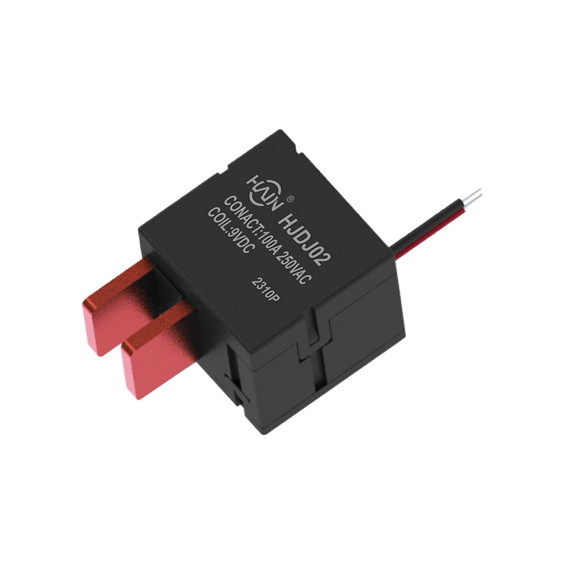
Product Definition: This product is a core control device designed for harsh industrial environments. Its key feature is its design specifically for high loads and complex electromagnetic environments...
See Details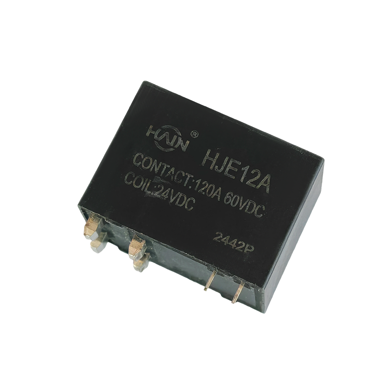
The Powerful Core of the PDU! The HJE12A-120A is a PCB-based through-hole high-power relay designed specifically for rack-mount power distribution units (PDUs), aiming to achieve PDU miniaturization, ...
See Details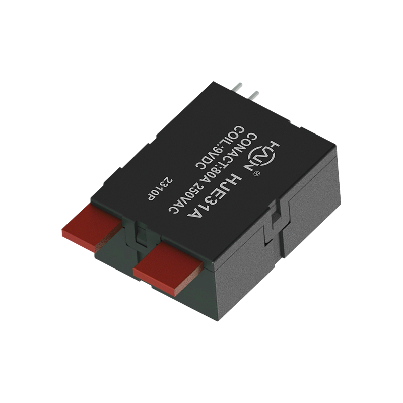
Product Definition: A bottom-in, bottom-out relay specifically designed for 2P DIN rail meters, aiming to improve installation efficiency and system reliability through optimized wiring structure.
See Details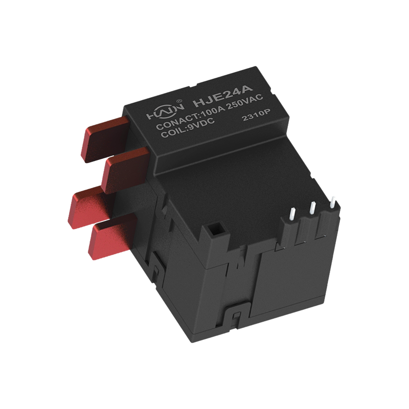
Dual-core drive, designed for demanding power control This is a high-current dual-channel relay compliant with UC3 safety standards, specifically designed for industrial scenarios requiring independen...
See Details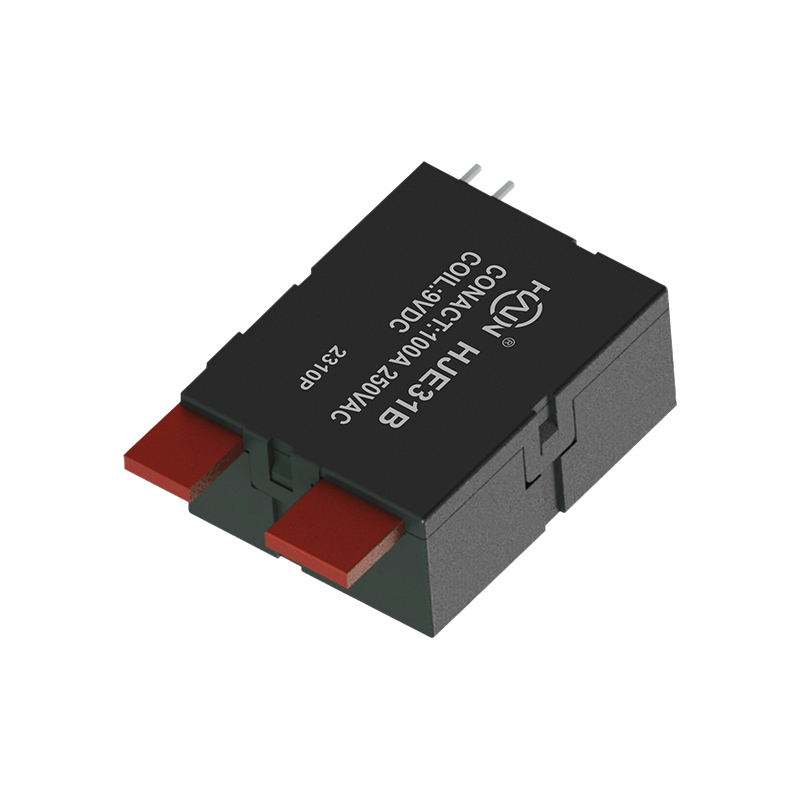
Product Definition: The HJE31B-100A is a split-type 7P DIN rail relay designed specifically for three-phase power systems. It features current monitoring, relay protection, and energy metering functio...
See Details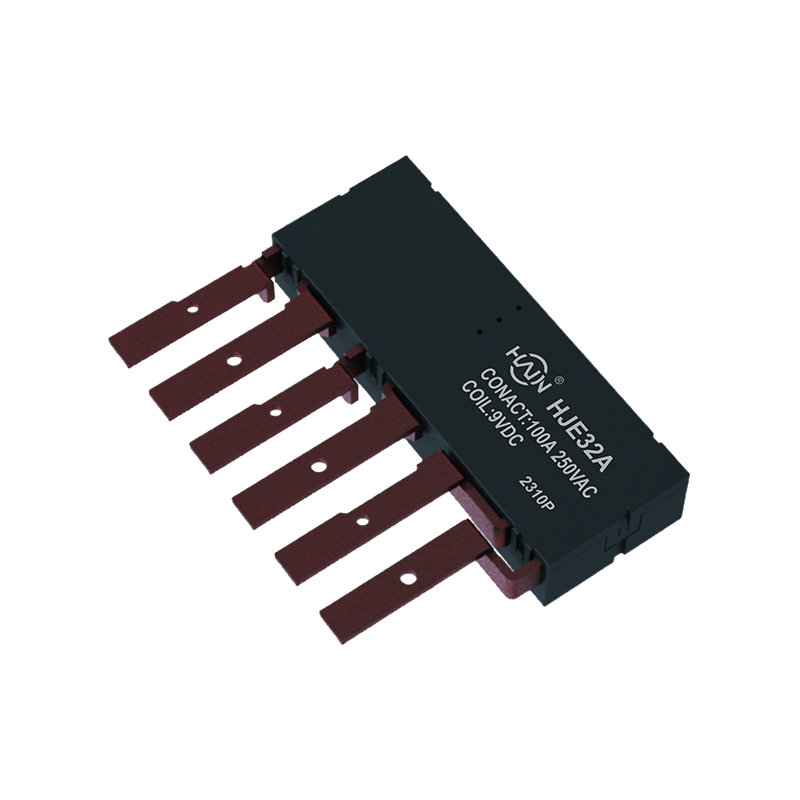
Product Definition: The HJE32A-100A is an innovative integrated three-phase relay designed specifically for 7P DIN rail meters. It aims to perfectly integrate three-phase metering and control, signifi...
See Details
 Add.
Add.
|
No. 707, Yanyu Road, Yucheng Town, Haiyan County, Jiaxing City, Zhejiang Province, China
|
 Phone
Phone
|
+86-188-5739-7300
|
 Email.
|
alio@hj-relay.com
|
Copyright @ Huajin Technology Jiaxing Co., Ltd. All rights reserved.

