



 English
 中文简体
 русский
NEWS
 Home / News / Industry News / DC Charging Station Relay Company: 48V 150A Latching Relay Sourcing Guide Home / News / Industry News / DC Charging Station Relay Company: 48V 150A Latching Relay Sourcing Guide
Content
Close the door on a 120 kW DC charging cabinet and the part most likely to be re-specified in year three is not the power module. It is the 48 VDC, 150 A latching relay that switches the low-voltage DC distribution path inside the cabinet, a component expected to survive roughly 21,000 operating events if the site averages six sessions a day across a ten-year service life. Three variables decide whether a supplier can support that duty: arc behaviour at the contact gap, contact resistance stability at rated current, and documentation an engineer can actually check.
A DC charging station relay interrupts direct current, so the arc never reaches the natural zero crossing that lets an AC contact clear itself. On a 50 Hz AC circuit the current passes through zero every 10 milliseconds and the arc extinguishes unassisted; on a DC circuit the arc keeps conducting until the contact gap and the arc control geometry stretch it far enough to cool.
That bistable behaviour is why latching relays sit in the switching position of charging cabinet PDUs. A 150 A relay that holds its state mechanically adds nothing to the cabinet's standing auxiliary load and nothing to internal temperature rise while the vehicle sits idle.
At 48 VDC the arc is short, but it is not absent. At 150 A the contact still has to absorb stored inductive energy from cabinet cabling and the capacitor bank behind it, and contact material selection matters more than the headline current figure suggests.
| Parameter | AC PDU latching relay | DC charging latching relay |
| Reference models | HJE11F120A250VAC, HJE12A120A250VAC | HJE12A150A48VDC |
| Contact system | 250 VAC | 48 VDC |
| Rated contact current | 120 A | 150 A |
| Arc behaviour at break | Extinguishes at the natural current zero | Sustained arc, stretched by contact geometry |
| Typical position in cabinet | AC output distribution unit | Low-voltage DC bus and auxiliary paths |
| Coil behaviour | Latching, pulse driven | Latching, pulse driven |
Read the AC and DC families as a pair rather than as substitutes. The 250 VAC models are described as latching relays for the PDU, while the 48 VDC model moves to a 150 A rating on a DC contact system. The wider EV charging station relay range splits along exactly that line, and a cabinet that mixes AC output distribution with a low-voltage DC bus needs both halves of it.
Contact current, contact resistance and coil voltage decide fitment before brand does, and of the three, contact resistance is the one that shows up in the thermal test rather than in the datasheet headline.
Every 0.1 milliohm of contact resistance dissipates 2.25 W at 150 A, because power equals current squared multiplied by resistance. A supplier declaring 0.5 milliohm maximum is describing 11.25 W of heat inside a sealed capsule before you add terminal and busbar losses; one declaring 1.0 milliohm is describing 22.5 W. Convert the declared maximum before you compare quotes, and ignore typical values entirely.
Coil voltage is the second screen. A 48 VDC coil has to pull in at the bottom of the auxiliary supply tolerance band, not at nominal, and it has to release cleanly when the driver drops the pulse. That behaviour is a tested window, not a line on a label.
Three document sets should be on your desk before a sample ships: an IEC 61810-1 endurance report at your rated load, a cabinet-level standard reference for the charging system, and an ISO 9001:2015 certificate whose scope names the relay family and model numbers.
| Standard or certificate | What it establishes | Document to request |
| IEC 61810-1 | Ratings, test conditions and endurance for electromechanical elementary relays | Load endurance report stating voltage, current and cycle count |
| IEC 61851-23 | System requirements for DC electric vehicle charging stations | Statement of the relay role in the cabinet type test |
| GB/T 18487.1 | General requirements for China's conductive charging system | Coil drive, interlock and insulation coordination notes |
| ISO 9001:2015 | Quality management system, independently audited | Certificate with scope statement, number and expiry date |
| CCC and TUV | Product level conformity for China market access and third party safety | Certificate listing the exact model numbers ordered |
Sequence the request so it cannot be answered with a brochure. Send the load profile first, then ask for the endurance report against it, then ask for the certificate scope page, then lock the change notification commitment. Each step produces a document you can file.
Annual volume, in-house assembly depth and engineering headcount predict delivery risk better than a price list, because in latching relays capacity decides whether a custom coil or a new contact material can be scheduled without moving your date.
Huajin Technology Jiaxing Co., Ltd. shows how to read those numbers. The company was registered in May 2021 with RMB 10 million in capital, runs an 8,000 square meter plant on Yanyu Road in Yucheng, Haiyan County, Jiaxing, Zhejiang, and employs more than 120 people. It states capacity above 10 million magnetic latching relays per year with roughly 30% of output exported, and lists 8 senior R and D engineers supported by a municipal level high-tech research centre. Quality documentation covers ISO 9001:2015, CCC, State Grid and TUV certification.
Platform reuse is the detail worth checking in any catalogue. The same HJE11B60A250VAC model appears under overvoltage, undervoltage and three-phase intelligent capacitor headings, and HJE31B100A appears under both DIN rail meter and multi-circuit headings. That is efficient engineering, one tooling set serving several device families, and it also means a contact material change made for a meter customer can land in the charging relay you are buying.
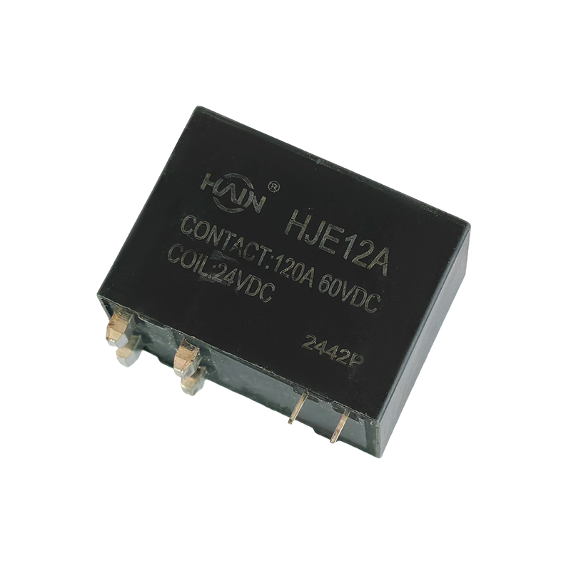 HJE12A-150A-48VDC Latching Relay for DC Charging150A/48VDC latching relay with double contacts, magnetic blowout and auxiliary status switch; its shared platform makes contact-material change control worth checking.View Product →
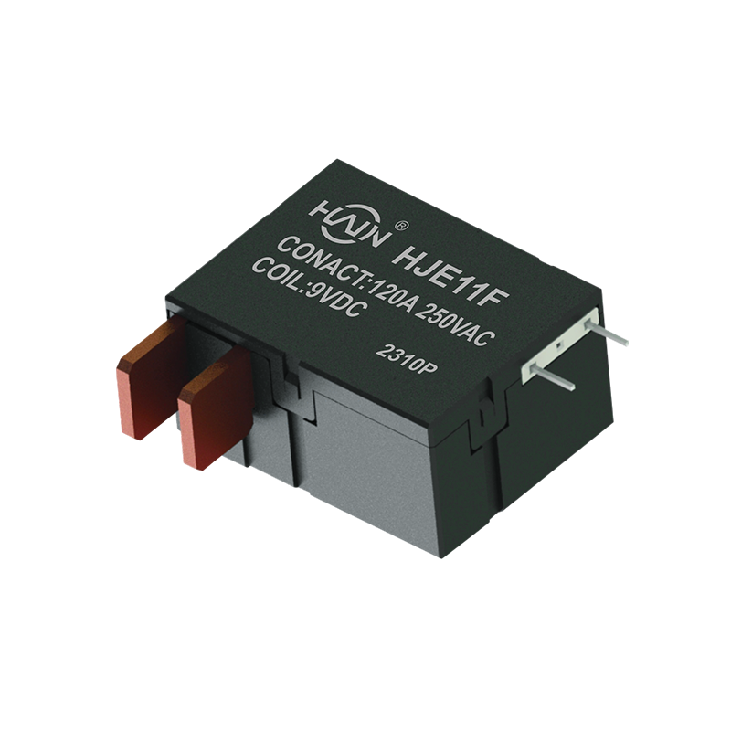 HJE11F-120A-250VAC Magnetic Latching Relay for PCB PDUs120A/250VAC PCB-mount magnetic latching relay with low coil power and 4kV isolation; platform reuse makes contact-material and change-control checks relevant.View Product →
Score five weighted criteria before you score price: DC load endurance at 30%, coil tolerance at 20%, change control at 20%, capacity and lead time at 15%, and certification scope at 15%.
| Criterion | Weight | Evidence to demand | Failure signal |
| DC load endurance | 30% | Endurance report at 48 VDC and rated current with a contact resistance trend | Only AC endurance data offered |
| Coil tolerance | 20% | Pull-in and drop-out window against the cabinet driver stage | Any coil voltage promised without test data |
| Change control | 20% | Written notification clause covering material and tooling | Verbal assurance only |
| Capacity and lead time | 15% | Annual volume in units plus current booking level | Volume quoted without a unit definition |
| Certification scope | 15% | Certificate naming the exact models ordered | Certificate covering a different product family |
The weighting is deliberate. Endurance carries the largest share because a DC contact failure is a field return with a truck roll attached, while a coil mismatch usually surfaces on the bench during the first power-up. Anything that cannot be evidenced in writing scores zero rather than a partial mark.
A 48 VDC, 150 A latching relay normally clears four gates in about fourteen weeks: sample selection, design validation, pilot run and serial release.
If the coil voltage, footprint or termination has to change, confirm the custom route early, because customized relay solutions usually add tooling lead time to gates three and four rather than to the sample stage.
48 VDC is the correct rating for low-voltage DC distribution and auxiliary paths inside the cabinet, which is the duty the HJE12A150A48VDC is built for; 250 VAC applies to the AC PDU side. Neither rating covers the 200 VDC to 1,000 VDC main charging output, which belongs to a different device class entirely.
Take 10 to 20 pieces from at least two production lots and run 2,000 operations at rated load on each, logging contact resistance every 500 cycles. Flag any unit whose final reading exceeds 1.5 times its own initial reading, because that pattern points to contact material or plating rather than to application error.
No. A 30% export share shows the supplier is set up for export packing, labelling and certificate translation. Build quality is proved by endurance data at 48 VDC and the rated current, plus a certificate whose scope lists the exact model number being ordered.
Require written notice at least 90 days before any change to contact material, plating, coil wire, magnet grade or housing tooling, with a right to re-qualify and to reject stock built to the changed design. That clause is what makes a ten-year service commitment enforceable.
Product Definition: The HJE12A-150A-48VDC is a high-performance DC relay designed specifically for 48VDC voltage systems, with a maximum current carrying capacity of 150A. It features excellent switch...
See Details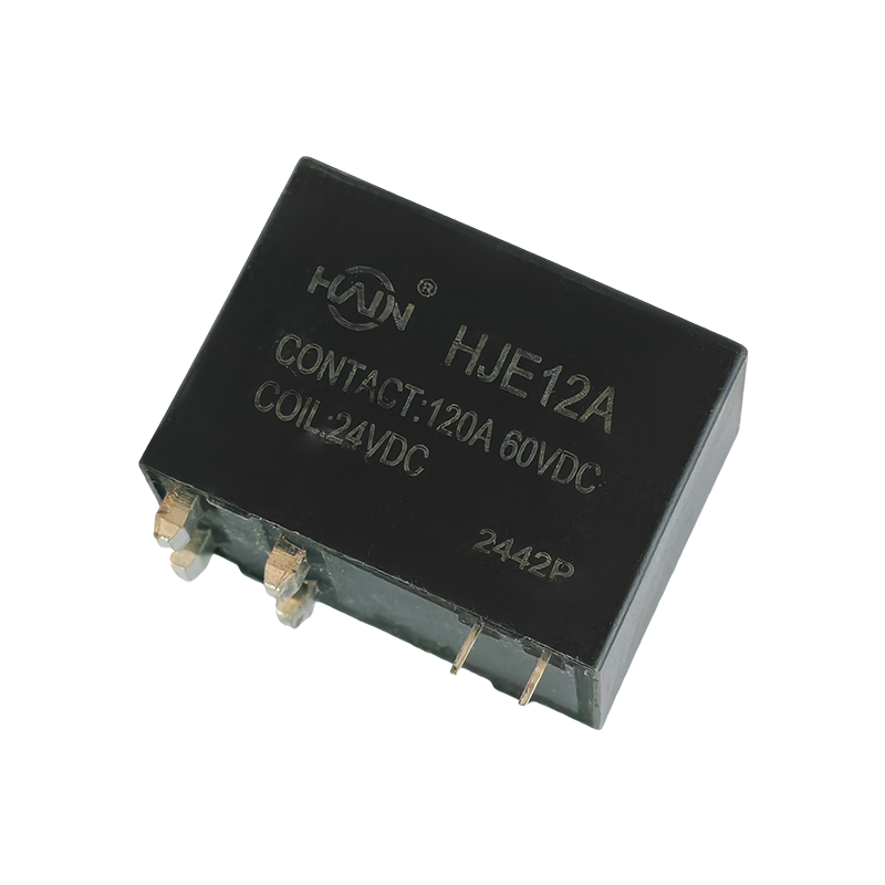
Product Definition: Designed specifically for 250VAC voltage systems, supporting a maximum current load of 150A. It employs advanced magnetic latching technology, maintaining the relay's state after a...
See Details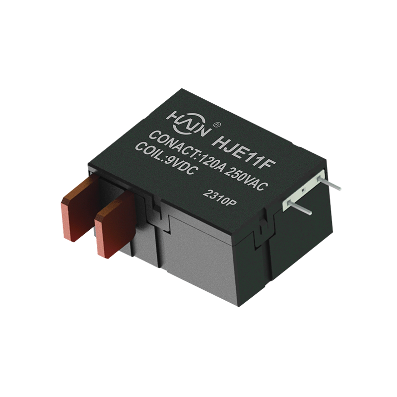
Product Definition: The HJE11F-120A-250VAC is a high-performance magnetic latching relay designed specifically for undervoltage protection systems. It supports a maximum current of 120A and is suitabl...
See Details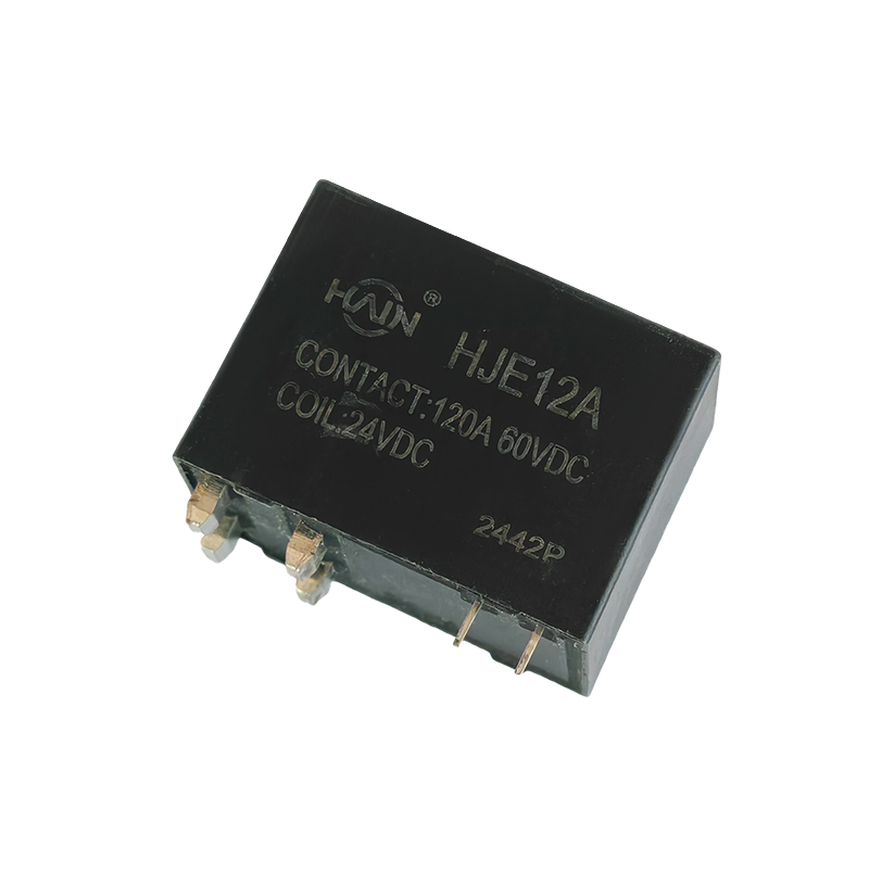
The Powerful Core of the PDU! The HJE12A-120A is a PCB-based through-hole high-power relay designed specifically for rack-mount power distribution units (PDUs), aiming to achieve PDU miniaturization, ...
See Details
Product Overview: Designed specifically for high-density power distribution units (PDUs), this high-power control core is directly integrated into the PCB board. With a robust 120A/250VAC load capacit...
See Details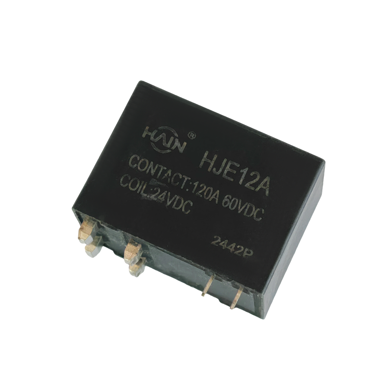
HJE12A-120A: Magnetic Latching Technology for Energy Saving and Reliability! The HJE12A-120A is a high-performance magnetic latching relay designed for power control systems requiring long-term stable...
See Details
 Add. |
No. 707, Yanyu Road, Yucheng Town, Haiyan County, Jiaxing City, Zhejiang Province, China
|
 Phone |
+86-188-5739-7300
|
 Email. |
alio@hj-relay.com
|
Copyright @ Huajin Technology Jiaxing Co., Ltd. All rights reserved.
