



 English
 中文简体
 русский
NEWS
 Home / News / Industry News / Energy Meter Relay Company: How to Vet Latching Relay Suppliers in 2026 Home / News / Industry News / Energy Meter Relay Company: How to Vet Latching Relay Suppliers in 2026
Content
A 120 A three-phase meter pushes its entire load current through one magnetic latching relay, and that relay has to break the circuit thousands of times without welding its contacts shut. Buyers who shortlist an energy meter relay company on unit price alone meet the real cost at type testing, when a 5,000-unit batch fails contact-resistance checks or the certificate turns out to cover a trading office instead of the plant.
The relay is a small share of the bill of materials, yet it controls three things the utility approval process examines closely: switching endurance, heat rise at rated current, and the traceability of the qualification file. The sections below follow the order an experienced hardware engineer actually runs them in.
An energy meter relay company supplies magnetic latching relays rated from 60 A to 150 A at 250 VAC, built for wall-mounted meters, DIN-rail meters, protection devices and charging equipment, and designed so the contact stays in its last position after a short coil pulse.
Definition: a magnetic latching relay is an electromechanical switch whose armature is held in its last position by a permanent magnet, so the coil draws current only during the set or reset pulse, typically a few milliseconds, and zero current while the contacts stay closed.
That behaviour drives the whole specification. A meter disconnect built this way consumes no holding power, which keeps the meter inside standby-loss limits and stops the coil from heating inside a sealed enclosure. The switching element also becomes a mechanical part of the meter, so its footprint, terminal layout and pole count matter as much as its current rating.
A working catalogue usually splits along two axes. The first is the end device: wall-mounted meter, DIN-rail meter, charging station, overvoltage and undervoltage protector, and smart capacitor. The second is the electrical circuit: single-phase, dual-circuit, three-phase and multi-circuit, each offered as split type, integrated type, vertical or compact housing, and with or without a shunt or shunt CT. The same base relay often appears in several application lists, because the model is qualified once and then re-documented for each platform. Huajin Technology Jiaxing Co., Ltd. publishes its meter-oriented range on the energy metering relays page.
UC2 and UC3 are the two utilization categories that decide which relays a meter platform can use: UC2 models in this catalogue stop at 60 A nominal, while UC3 models cover 100 A to 150 A and appear in three-phase, 7P DIN-rail and high-current single-phase designs.
Both categories trace back to IEC 62055-31, the part of the IEC 62055 series that sets out the internal switching requirements of electricity metering equipment. The category fixes the current, the number of operating cycles and the fault conditions the switch must survive, so a UC3 meter cannot be dropped onto a UC2 relay to save cost without re-qualifying the entire platform.
| Selection factor | UC2 relays | UC3 relays |
| Nominal switching current | 60 A at 250 VAC | 100 A to 150 A at 250 VAC |
| Typical meter platform | Single-phase wall-mounted, 2P DIN rail | Three-phase, 7P DIN rail, high-current single-phase |
| Circuit configurations | Single-phase, dual-circuit, multi-circuit | Dual-circuit, three-phase, large-current single-phase |
| Main engineering risk | Contact wear under frequent switching | Terminal heat rise and busbar routing |
| Catalogue references | HJE11B60A, HJE21A60A | HJE11F120A, HJE24A100A, HJE33C120A |
Why the step from 60 A to 120 A is physical, not commercial: contact loss scales with the square of the current. At identical contact resistance, a 120 A load dissipates four times the heat of a 60 A load, so a UC3 body differs in contact material, terminal geometry and housing volume.
The single-phase UC3 end of the range is where most first orders land: 120 A at 250 VAC inside a body that still fits a wall-mounted meter envelope.
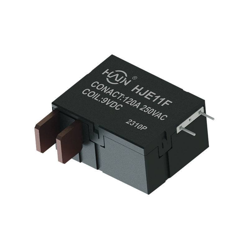 HJE11F-120A Single-Phase Latching Relay for Metering120 A at 250 VAC UC3 single-phase relay with low coil power, 4 kV coil-to-contact isolation, and PCB termination for smart-meter and load-control designs.View Product →
Five checks settle the question in one supplier visit: certificate scope, model-to-application mapping, contact rating against the meter's declared category, capacity expressed in units per year, and a documented customization route.
The catalogue's 250 VAC contact range runs 60 A, 80 A, 90 A, 100 A, 120 A and 150 A, and each step maps to a different meter format rather than to a marketing tier.
Reading upward, 60 A covers single-phase wall-mounted and multi-user metering, 80 A to 100 A covers dual-circuit and 2P DIN-rail designs, and 120 A to 150 A belongs to three-phase and large-current single-phase platforms. The same ladder continues into DC: a 48 VDC, 150 A body carries the charging current of a DC charging post, where the coil pulse has to work against a very different contact load.
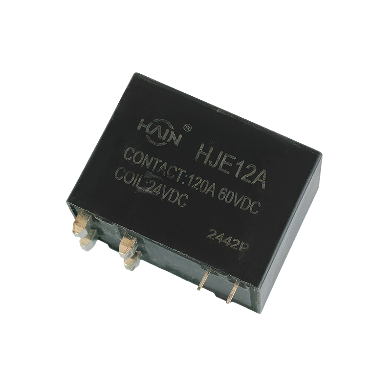 HJE12A-150A-48VDC Latching Relay for DC Charging150 A 48 VDC relay with double contacts and magnetic blowout, an auxiliary status switch, and no load polarity requirement for DC power and charging systems.View Product →
Split type relays place the contact set and the current path in separate housings so the meter designer routes the busbar, while integrated types carry the shunt CT inside the relay body and remove one assembly step from the meter line.
Dual-circuit platforms sit in the middle of that decision. A dual-channel body rated 100 A per channel removes two separate relays and their wiring from a two-user DIN-rail meter, which is why large-current dual-channel models have become the default for multi-occupancy metering.
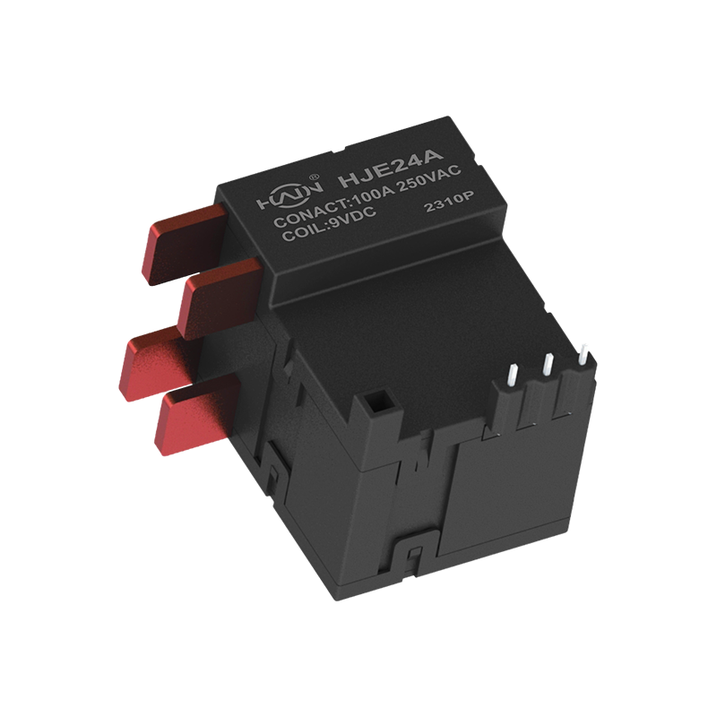 HJE24A-100A Dual-Channel Latching Relay for DIN Rail MetersTwo independent 100 A channels in one UC3-compliant body support dual-circuit DIN-rail metering, with magnetic latching and zero static coil power.View Product →
Three numbers decide delivery risk in this category: annual capacity above 10 million relays, a plant of 8,000 square meters with more than 120 staff, and an export share of about 30% that keeps overseas approval documents current.
Certification is the second half of the same picture. ISO 9001:2015 covers the management system, CCC covers domestic safety, and TUV or State Grid approval covers the utility-facing programs. A supplier that holds all four can usually supply the test report that goes with them, which is what your meter certification body will ask for.
At minimum ISO 9001:2015 for the manufacturing site, CCC for the domestic market, and TUV plus State Grid approval for utility programs. Ask for the certificate number and the address printed in the scope, because a certificate naming a trading office rather than the plant does not cover the relays you will receive.
Start from the meter's rated current and its declared utilization category. A 60 A single-phase wall-mounted platform fits a UC2 body such as HJE11B60A; a 100 A platform needs a UC3 body, because the contact set and terminal block must handle about 2.8 times the resistive loss at equal contact resistance.
Plan on a 10 to 14 week window from specification freeze to volume shipment. Drawing approval, a pilot batch and a type test on the finished meter consume most of it; annual capacity above 10 million relays is rarely the constraint, tooling and qualification are.
Yes, and it is routine. A 250 VAC latch such as HJE11B60A appears in overvoltage, undervoltage and three-phase smart capacitor lists because the switching duty is comparable, which shortens the approval path and reduces the number of part numbers a meter maker has to carry.
The relay is the cheapest component in a meter that can stop a type test, and the only one whose failure is visible to the end user as a meter that will not disconnect. Vet the supplier on certificate scope, category fit, current ladder and capacity in units, and the price conversation becomes a much shorter one.
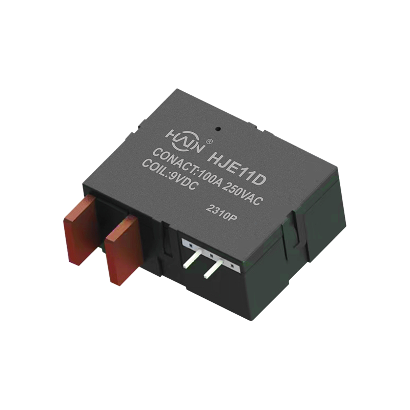
Redefining the DIN rail meter, one chip solves two major problems! The HJE11D-100A is a high-current relay with metering function designed specifically for 4P DIN rail energy meters. It aims to solve ...
See Details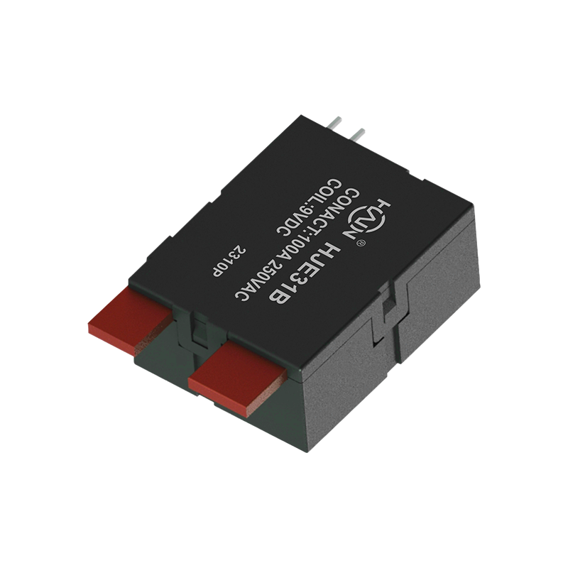
Product Definition: The HJE31B-100A is a split-type 7P DIN rail relay designed specifically for three-phase power systems. It features current monitoring, relay protection, and energy metering functio...
See Details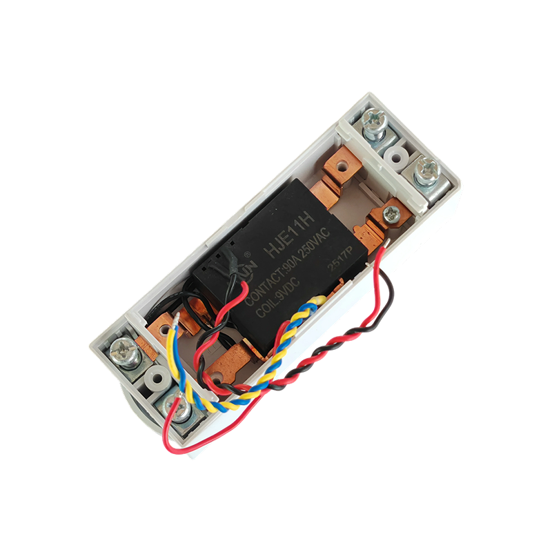
Product Definition:This product is a top-in, bottom-out 2-pole DIN rail relay designed specifically for modern power distribution systems. It integrates a 90A high current carrying capacity, compact s...
See Details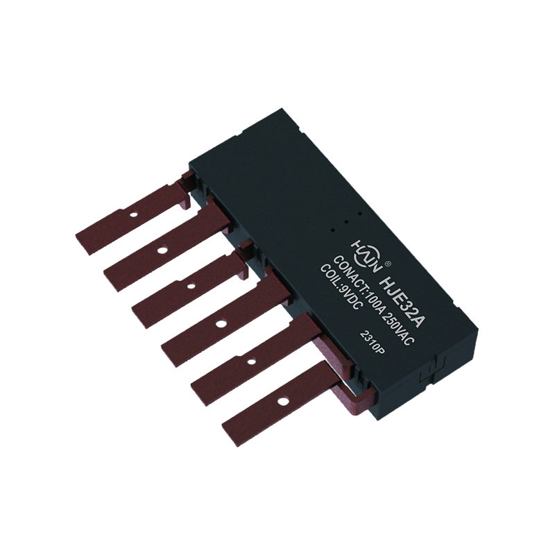
Product Definition: The HJE32A-100A is an innovative integrated three-phase relay designed specifically for 7P DIN rail meters. It aims to perfectly integrate three-phase metering and control, signifi...
See Details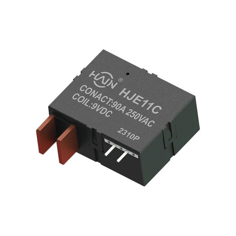
Product Definition: This product is a four-pole DIN rail relay integrating power metering and relay protection functions. Designed specifically for power metering systems, it is widely used in residen...
See Details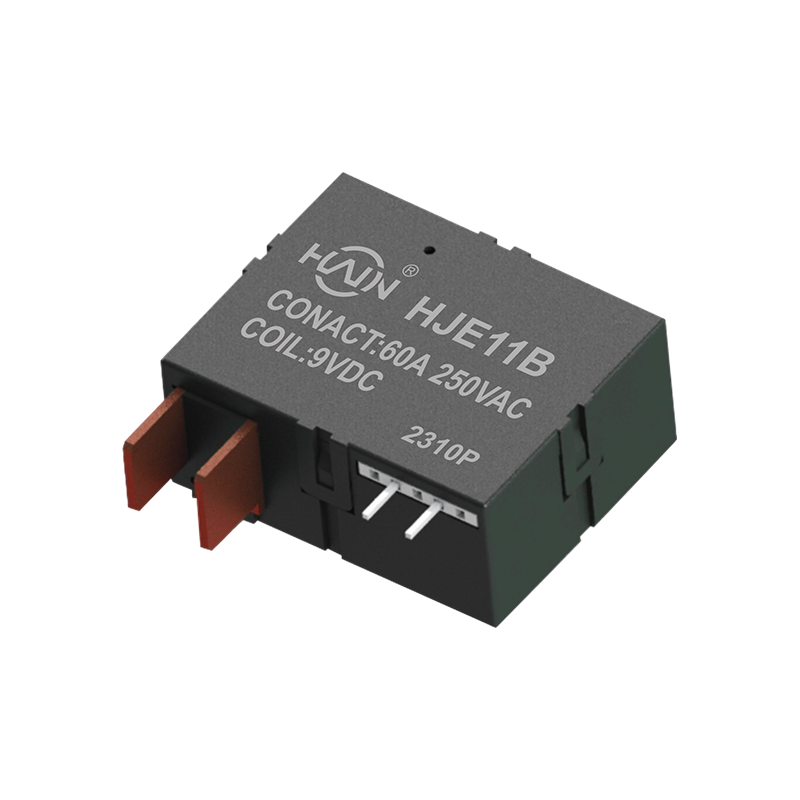
A Power Management Expert Integrating Control and Metering In increasingly complex industrial and commercial power distribution environments, refined power management and reliable control are equally ...
See Details
 Add. |
No. 707, Yanyu Road, Yucheng Town, Haiyan County, Jiaxing City, Zhejiang Province, China
|
 Phone |
+86-188-5739-7300
|
 Email. |
alio@hj-relay.com
|
Copyright @ Huajin Technology Jiaxing Co., Ltd. All rights reserved.
