



 English
 中文简体
 русский
NEWS
 Home / News / Industry News / Magnetic Latching Relay Guide: Coil Drive, Key Specs and Meter Selection Home / News / Industry News / Magnetic Latching Relay Guide: Coil Drive, Key Specs and Meter Selection
Content
Hold a 100 A non-latching power relay closed at 12 V and it will draw roughly 2 W and run warm for as long as the meter stays energized. A magnetic latching relay deletes that current: the coil fires for a pulse of 30 to 100 ms, a permanent magnet takes over, and steady-state coil power drops to 0 W.
That single difference is why bistable designs now occupy the load-switch position in smart electricity meters, DIN rail meters, charging pile PDUs, over and under-voltage protectors and three-phase smart capacitors. It is also why so many field failures trace back to the drive circuit rather than to the contacts themselves.
A magnetic latching relay is a bistable electromechanical switch. A short current pulse moves the armature, a permanent magnet holds the contacts in the new position, and the relay stays there after the drive signal disappears.
Magnetic latching relay: an electromechanical relay whose contact state is maintained by a permanent magnet instead of continuous coil current. Only the transition consumes energy; the latched state consumes none.
Compare that with a standard non-latching relay, which needs a constant coil voltage to stay closed. Two holding mechanisms are sold under the latching label. Magnetic latching relays hold with a permanent magnet, which works in any mounting orientation and never needs a release force. Mechanical latching relays hold with a spring and detent; they appear in low-power signalling circuits but rarely in meter load switches, where the holding force has to survive vibration and a decade of thermal cycling.
Changing state takes one of two arrangements. A dual-coil relay has separate set and reset windings. A single-coil relay uses one winding with reversed current direction. In both cases the drive signal is a pulse, not a level, and three system-level consequences follow.
Dual-coil wins when the board can afford two drivers; single-coil wins when terminal count and package size are the binding constraint. The contact side of the specification is usually identical, so the real decision sits in the control circuit.
Pulse width is a design parameter, not a suggestion. Meter-class coils need roughly 30 to 100 ms at rated coil voltage to complete armature travel. A pulse shorter than about 20 ms risks an incomplete stroke that surfaces months later as intermittent closed-state failures; a pulse longer than about 200 ms adds coil heat without improving contact force.
Rated contact current is the number buyers compare first, but contact resistance drift, dielectric margin and pulse energy cause most warranty returns. Review these six items before approving a part number.
| Specification | What to verify | Consequence if underspecified |
| Contact current rating | Confirm the rating at the ambient inside the enclosure, not on a 25 C bench | Terminal heating and discoloration in year three |
| Contact resistance | Ask for batch distribution data instead of a single sample | Meter accuracy drift and calibration callbacks |
| Dielectric strength | Coil-to-contact margin in the 4 kV class for meter applications | Certification rejection at State Grid or TUV stage |
| Coil pulse width | 30 to 100 ms measured on your own driver board | Incomplete switching, contact chatter, welded contacts |
| Electrical life | 100,000 operations is a common floor for a meter load switch | Warranty returns in years three to five |
| Magnetic immunity | Anti-magnetic construction for positions near current transformers | Unintended state changes under external field |
Take the single-phase wall-mounted meter case. A 120 A UC3-class part such as the HJE11F120A covers the top of that range, and the number that decides field reliability is not the headline current rating but the resistance band held across a full production batch.
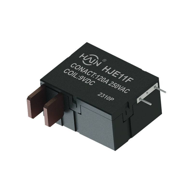 HJE11F-120A Single-Phase Magnetic Latching Relay for High-Power ControlA 120 A UC3-class PCB relay for smart meters and high-power equipment, with magnetic latching, low coil power, and stable batch resistance.View Product →
Match the relay to the load profile, not to the current number alone. A meter may switch twice a day, while a charging pile PDU may carry 120 A for eight hours, and those two duty cycles stress the same component in completely different ways.
| Application | Typical rating | Selection focus |
| Wall-mounted meter, single phase | 60 to 150 A, 250 VAC | UC2 or UC3 compliance and terminal geometry for the meter base |
| Wall-mounted meter, three phase | 100 to 120 A, 250 VAC | Balanced three-pole travel and 25th edition State Grid coverage |
| DIN rail meter, 2P to 7P | 80 to 100 A, 250 VAC | Split type versus integrated with shunt CT, plus rail height |
| Multi-user meter | 60 to 80 A, 250 VAC | Channel isolation inside a single housing |
| AC charging pile PDU | 120 A, 250 VAC | Continuous-duty margin across long charging sessions |
| DC charging pile | 150 A, 48 VDC | DC arc control and terminal thermal design |
| Over and under-voltage protector | 60 to 150 A, 250 VAC | Fast release and self-locking behaviour |
DIN rail meters add a mechanical constraint that wall-mounted meters do not have. The relay has to sit behind a 2P, 4P or 7P rail enclosure, which is why split-type constructions such as the HJE11B60A exist: the switching element and the shunt CT sit in separate mouldings so the assembly stacks into a standard rail footprint.
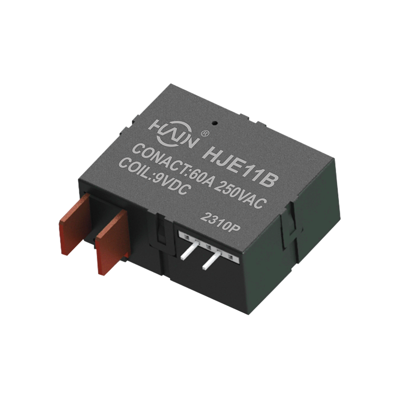 HJE11B-60A Split-Type Combined Latching Relay for DIN Rail MeteringA 60 A split/modular latching relay for DIN rail meters, separating switching element and shunt CT to fit standard 2P to 7P enclosures.View Product →
Charging piles and protection devices load a latching relay thermally rather than mechanically, and that flips the specification priority.
Inside an AC charging pile, the PDU relay carries 120 A at 250 VAC for hours at a stretch in a sealed enclosure where summer ambient can reach 60 C. Continuous-duty margin, terminal cross-section and copper area on the board matter more than switching life, because the relay may only operate a few times a day. The HJE11F120A250VAC is built for exactly that PDU position, with the 250 VAC rating stated in the part number rather than inferred from a family datasheet.
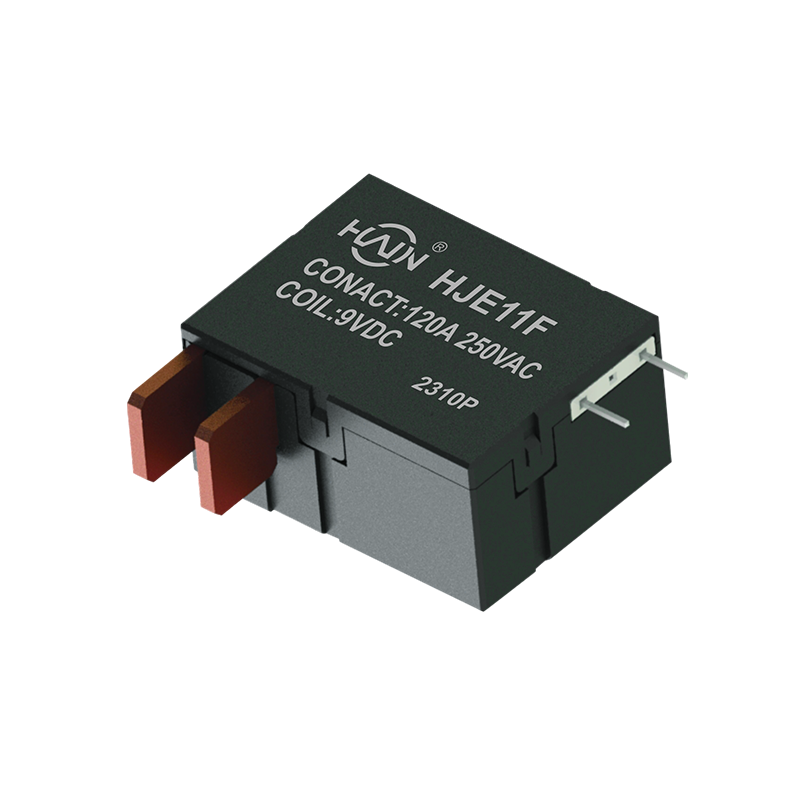 HJE11F-120A-250VAC Latching Relay for AC Charging Pile PDUA 120 A 250 VAC PCB relay for charging pile PDUs, offering continuous-duty margin and high-density power distribution in sealed enclosures.View Product →
DC piles push the problem in another direction. The HJE12A150A48VDC carries 150 A at 48 VDC, where arc extinction and terminal heating need explicit attention instead of a copy of an AC layout. Over and under-voltage protectors and three-phase smart capacitors then behave like meters with faster trigger logic. The same 60 A to 150 A, 250 VAC platform reappears across all three families, which is why component reuse between them is practical rather than optimistic.
The relay is the highest-current component on most meter and pile assemblies, so supplier qualification is a program-level decision rather than a purchasing line item.
Huajin Technology Jiaxing Co., Ltd. builds its volume around magnetic latching relays and publishes ISO 9001-2015, CCC, State Grid and TUV credentials for the parts it supplies into metering programs. The company operates from a facility in Yucheng, Haiyan County, Jiaxing, with a municipal-level high-tech R&D centre and eight senior R&D engineers behind the customised variants.
Before releasing a purchase order, confirm five things.
Selection support is worth using early. The DIN rail meter relay selection guide walks through split-type versus integrated formats, and the product matrix published by Huajin Technology Jiaxing Co., Ltd. maps part numbers to enclosure formats, which shortens the gap between a mechanical design freeze and a qualified relay.
No. Steady-state coil power is 0 W. Current flows only during the set or reset pulse, typically 30 to 100 ms, so the coil contributes no continuous heat load inside a sealed enclosure.
Most meter-class coils complete armature travel in 30 to 100 ms at rated coil voltage. Pulses shorter than about 20 ms risk an incomplete stroke, while pulses longer than about 200 ms add coil heat without increasing contact force.
Only if the drive circuit changes. The relay needs a pulse driver, an H-bridge for a single-coil part or two low-side drivers for a dual-coil part, plus a reservoir capacitor. The contact side usually drops in unchanged when terminal geometry matches.
Match the meter basic current and the standard it must satisfy. Three-phase DIN rail latching relays are commonly specified between 80 A and 120 A at 250 VAC in split-type and integrated-with-shunt-CT formats, with the 25th edition State Grid variant at 120 A.
The relay is usually the last component to be questioned and the first to be blamed. Specifying the pulse drive, the contact resistance band and the certification scope at quotation stage removes most of that ambiguity before the first production batch ships.
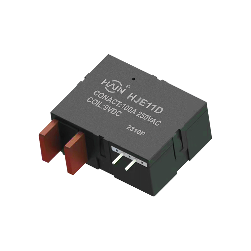
Redefining the DIN rail meter, one chip solves two major problems! The HJE11D-100A is a high-current relay with metering function designed specifically for 4P DIN rail energy meters. It aims to solve ...
See Details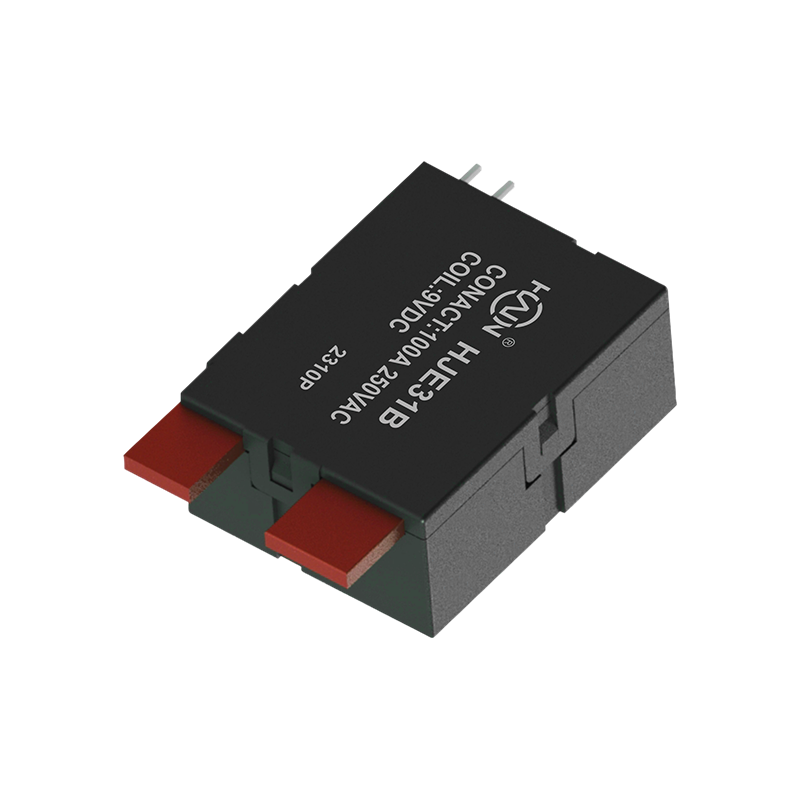
Product Definition: The HJE31B-100A is a split-type 7P DIN rail relay designed specifically for three-phase power systems. It features current monitoring, relay protection, and energy metering functio...
See Details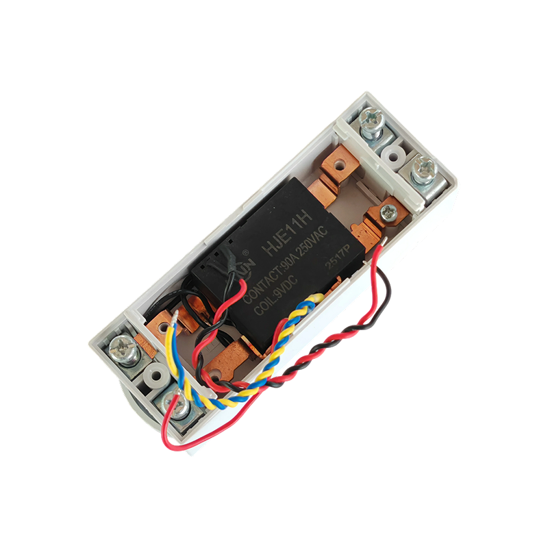
Product Definition:This product is a top-in, bottom-out 2-pole DIN rail relay designed specifically for modern power distribution systems. It integrates a 90A high current carrying capacity, compact s...
See Details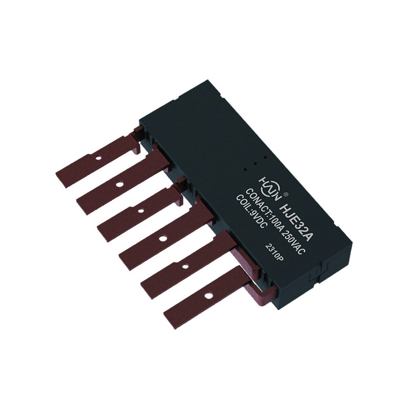
Product Definition: The HJE32A-100A is an innovative integrated three-phase relay designed specifically for 7P DIN rail meters. It aims to perfectly integrate three-phase metering and control, signifi...
See Details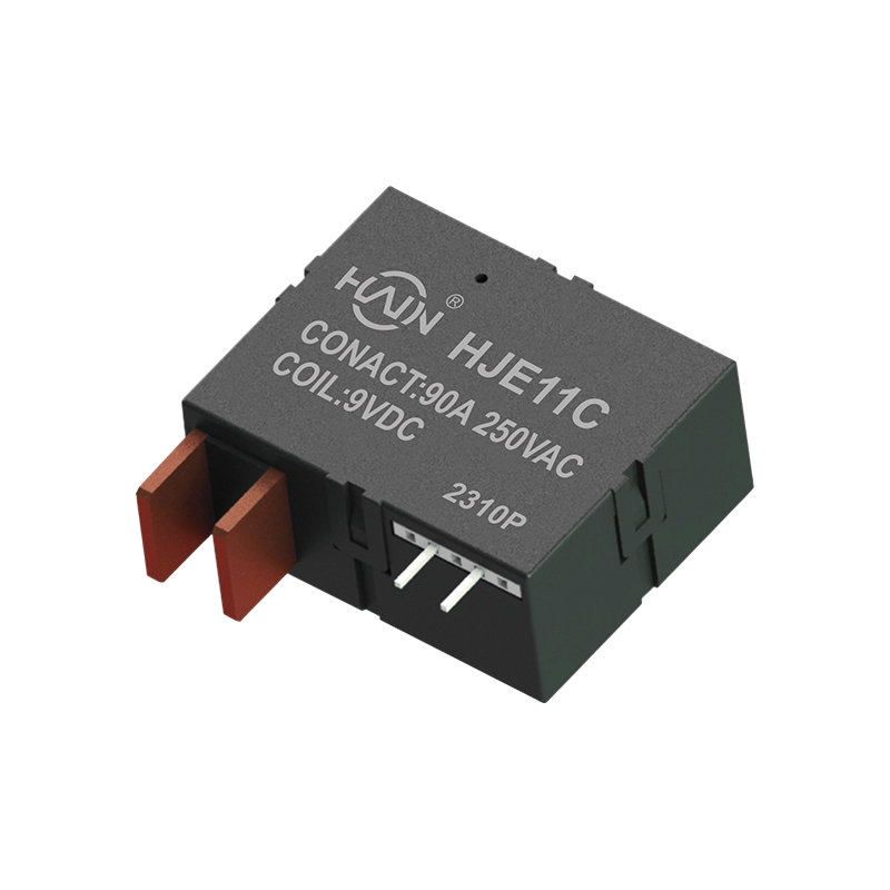
Product Definition: This product is a four-pole DIN rail relay integrating power metering and relay protection functions. Designed specifically for power metering systems, it is widely used in residen...
See Details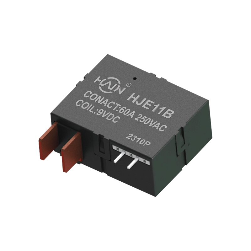
A Power Management Expert Integrating Control and Metering In increasingly complex industrial and commercial power distribution environments, refined power management and reliable control are equally ...
See Details
 Add. |
No. 707, Yanyu Road, Yucheng Town, Haiyan County, Jiaxing City, Zhejiang Province, China
|
 Phone |
+86-188-5739-7300
|
 Email. |
alio@hj-relay.com
|
Copyright @ Huajin Technology Jiaxing Co., Ltd. All rights reserved.
