



 English
 中文简体
中文简体 русский
NEWS
Content
A Multi Circuit Meter Relay is the small but essential component that lets a single wall-mounted energy meter keep track of several electrical circuits at once, instead of requiring a separate meter for every load it needs to measure. It sits quietly between the wiring and the meter itself, switching and routing signals so that one metering point can report on many circuits without confusing them together, and that quiet job turns out to matter a great deal in buildings where electricity use needs to be measured circuit by circuit rather than as one combined total.
To understand this device, it helps to break the name into its three separate working parts, each of which plays a distinct role in how the whole system functions. A "circuit" is simply a closed loop of wiring that carries electricity to a single load, such as one apartment unit, one appliance line, or one piece of equipment. A "meter" is the instrument that measures how much electrical energy passes through a circuit over time. A "relay," in the electrical sense, is a switch that opens or closes a connection automatically, usually controlled by a small electrical signal rather than a person flipping it by hand.
Put those three ideas together, and a multi circuit meter relay becomes a device that manages the connection between several separate circuits and a shared metering system, switching between them or routing their signals so that one meter can read multiple circuits accurately, either sequentially or through a set of individually monitored channels, depending on how the specific unit is designed. Rather than wiring an entire meter to every single circuit in a building, which would be expensive and space-consuming, a single meter can be paired with a relay unit that handles the multiplexing, meaning it manages several inputs through one shared measuring instrument.
This approach is especially common anywhere a building operator needs to see usage broken down by unit, tenant, or piece of equipment, rather than as one combined number. A relay of this kind acts like a traffic controller for electrical measurement: it does not generate the readings itself, but it makes sure the right circuit is being measured at the right moment, and that the data does not get crossed between circuits.
It is worth pausing on why this matters in the first place. Electricity, once it reaches a building, is rarely used by just one thing. A single wall-mounted meter installed at the point where power enters a property can only report a combined total unless something downstream separates that total back out into meaningful pieces. Without a way to distinguish between circuits, a property manager would have no accurate way to know how much a particular unit, tenant, or system actually consumed, which becomes a real problem the moment billing, budgeting, or troubleshooting depends on that information. A multi circuit meter relay exists specifically to close that gap, turning one shared connection point into several individually accountable streams of data.
A multi circuit meter relay is best understood as a switching and routing device that allows one energy meter to accurately measure multiple electrical circuits, rather than a meter itself.
The internal process behind this kind of device can be explained as a short sequence of stages, moving from raw electrical current at each individual circuit through to a clean, correctly labeled number appearing on the meter's display.
Each individual circuit is fitted with a small sensor, most commonly a current transformer, which detects how much electrical current is flowing through that specific line without needing to physically interrupt the wiring.
The relay unit receives signals from each connected circuit and determines which one should be passed through to the meter at any given moment, either by cycling through them in sequence or by directing each one to a dedicated measurement channel.
The switching itself happens on the low-power signal side of the system rather than on the main current-carrying conductors, which means circuits continue supplying power to their loads uninterrupted while the relay simply manages which signal is being read.
The meter receiving the routed signal logs the reading against the correct circuit identity, so that even though one physical meter is doing the measuring, the resulting data stays organized by individual circuit.
Depending on the design, the relay either continues cycling through all connected circuits on a set interval or updates each dedicated channel continuously, keeping the readings current without requiring manual switching.
Specification sheets for relay and metering equipment can look intimidating at first glance, but each figure answers a fairly simple practical question about how the device behaves in real conditions.
| Number of circuits supported | How many individual loads a single relay unit can manage, commonly ranging from two to twelve depending on the model |
| Rated current per channel | The maximum current a single circuit connection can safely handle before the relay or sensing component is at risk of damage |
| Switching speed | How quickly the relay can move from reading one circuit to reading the next, usually measured in milliseconds |
| Sensing method | Whether current is measured using a current transformer, a shunt resistor, or another sensing approach, which affects accuracy and installation method |
| Mounting format | Whether the unit is designed for standard DIN rail mounting inside an electrical panel or a different enclosure style |
| Communication protocol | How the relay or meter sends data onward, such as through a wired serial connection or a networked protocol, when remote monitoring is part of the setup |
| Operating voltage range | The range of supply voltage the relay itself needs to operate correctly, separate from the voltage of the circuits it is monitoring |
The two figures worth paying closest attention to are the number of supported circuits and the rated current per channel, since together they determine whether a single relay unit can realistically cover a given installation or whether multiple units will be needed. A relay rated for six circuits at a modest current level, for instance, is not a smaller version of a twelve-circuit unit; it reflects a genuinely different intended scale of installation, from a small multi-unit residence up to a larger commercial floor.
Switching speed is another figure that is easy to skim past, but it directly affects how current the data actually feels in practice. A relay that cycles through connected circuits every few seconds will produce readings that update noticeably slower than one built around dedicated, continuously updating channels for each circuit. For simple billing purposes, a modest cycling speed is usually more than sufficient, but for applications where near-real-time visibility matters, such as tracking sudden load changes at an equipment room, a faster-updating configuration becomes considerably more useful.
Beyond the raw specification numbers, several practical considerations tend to shape which relay configuration actually makes sense for a specific installation.
Total circuit count today versus future growth. A property with eight circuits today but plans to expand may be better served by a relay with some spare capacity built in, since adding circuits later often costs less than replacing an undersized unit entirely.
How the data will be used. A simple monthly billing use case has very different requirements than a monitoring system meant to flag unusual usage patterns as they happen, and that difference should guide decisions around switching speed and communication protocol.
Physical panel space. DIN rail mounted units are compact, but available space inside an electrical panel still varies significantly between older and newer installations, which can influence which physical form factor is realistic to install.
Existing wiring and sensor compatibility. Retrofitting a relay into a building with existing current transformers already installed is generally more straightforward than a full new installation, and confirming compatibility ahead of time avoids unnecessary rework, delays, or the added expense of replacing sensors that would otherwise have worked perfectly well.
The clearest way to understand the value of a multi circuit approach is to compare it directly against the alternative of metering each circuit with its own separate, standalone meter.
Neither approach is inherently superior in every situation. A single building with only two or three circuits to monitor may not gain much from the added complexity of a relay-based system, while a property with a dozen or more individually billed circuits, such as a multi-tenant building, typically sees a meaningful reduction in equipment cost and panel space by consolidating measurement through one relay-connected meter. The decision ultimately comes down to weighing the modest added setup effort of a relay-based system against the ongoing cost and space savings it provides as circuit count grows.
Once the underlying function is clear, it becomes easier to recognize the settings where this kind of equipment shows up most often.
Apartment buildings and multi-unit residences often need to bill electricity usage separately per unit, and a Multi Circuit Meter Relay allows one central meter to track each unit's consumption individually.
Sites with several charging points sharing one electrical connection benefit from relay-based metering to track and, in some setups, manage how each charging point draws from the shared supply.
Installations with multiple strings or subsystems feeding into one system often use relay-based metering to keep performance data separated by section rather than blended into a single combined figure.
Office floors or retail spaces with several independently leased sections can use a shared metering setup to allocate usage accurately without installing a dedicated meter body for every tenant.
Rooms housing multiple pieces of equipment on separate circuits sometimes use multi circuit monitoring to track which specific equipment lines are drawing the most power over time.
Properties with several separately powered outbuildings or systems, such as irrigation pumps and storage facilities, can consolidate monitoring through one relay-connected meter rather than wiring a full meter to each structure.
Installing a multi circuit meter relay is generally handled by a qualified electrician, since it involves connecting sensing components to live electrical circuits and wiring the relay itself into the panel correctly. The process usually starts with identifying which circuits need individual tracking, followed by fitting each one with its sensing component, most often a current transformer clamped around the relevant conductor without needing to cut into the wiring itself.
Once the sensors are in place, each one is wired back to the relay unit, which is then connected to the meter that will ultimately display or record the readings. Configuration at this stage often involves labeling each channel so that readings can be matched back to the correct circuit later, which matters a great deal when the data will be used for billing or reporting rather than casual observation.
Ongoing upkeep for these systems tends to be relatively light compared to the equipment they replace. Because there are no moving mechanical parts involved in the sensing itself, and the switching happens on a low-power signal path rather than the main current-carrying conductors, wear and tear is generally limited. Periodic checks typically focus on confirming that readings still line up with expected usage patterns and that connections remain secure, rather than any deep mechanical servicing.
| Myth | Reality |
| A relay is the same thing as a meter. | A relay only switches or routes signals; the actual measurement of energy use is still performed by the connected meter itself. |
| More circuits always means better value. | A relay's usefulness depends on matching its circuit capacity to the actual number of loads being monitored, not simply choosing the highest-capacity option available. |
| Switching between circuits interrupts power to them. | The switching happens on the measurement signal path, not on the main power-carrying conductors, so connected loads keep running normally throughout. |
| All multi circuit systems use the same sensing method. | Current transformers and shunt-based sensing are both used across different products, and the choice affects installation requirements and measurement characteristics. |
Electrical metering has existed since the late nineteenth century, originally designed around the simplest possible case: one meter, one customer, one combined load. That approach worked well for individual homes and small businesses, but it ran into a practical wall as buildings grew larger and more subdivided. Apartment blocks, shared commercial floors, and increasingly complex facilities all created a situation where a single combined reading was no longer detailed enough for fair billing or useful monitoring.
The earliest response to this problem was simply installing more meters, one for every circuit or unit that needed separate tracking. That solution works, but it scales poorly, since every additional meter adds cost, panel space, and wiring complexity. As electronics and current-sensing technology matured through the twentieth century, it became possible to separate the job of sensing current from the job of displaying and recording it, which opened the door to shared metering systems where a relay component could manage multiple sensing points feeding into fewer actual meter bodies.
Today, as buildings and installations continue to demand more granular data, from individual apartment billing to per-circuit equipment monitoring, multi circuit relay-based metering has become a practical middle ground between the high cost of installing a full meter everywhere and the limited usefulness of one combined reading for an entire building.
This shift also reflects a broader change in how buildings are managed day to day. Decades ago, a single combined utility bill for an entire property was simply accepted as the norm, with costs divided among tenants through estimates or flat allocations rather than actual measured use. As energy costs rose and expectations around fairness and transparency increased, the demand for accurate, circuit-level data grew alongside them. Multi circuit relay systems became one of the more practical technical responses to that shift, offering granular measurement without requiring every building to be rewired around a meter for every single load.
A multi circuit meter relay is not a specialized or unusual piece of equipment; it is a practical solution to a very ordinary problem, which is how to measure several separate electrical circuits accurately without installing a dedicated meter for each one. By handling the switching and routing between circuits, a Multi Circuit Meter Relay allows one meter to do the work that would otherwise require several, keeping installations more compact and cost-efficient wherever circuit-level detail actually matters.
Recognizing whether a given installation genuinely needs multi circuit capability comes down to one simple question: does usage need to be understood and reported separately for each circuit, or is one combined figure enough? Buildings and systems with several independently used or independently billed circuits tend to benefit clearly from this approach, while smaller, simpler setups may not need the added capability at all.
As with most equipment decisions, the right answer depends less on the most advanced option available and more on matching the device's capacity and configuration to how the space is actually used. A clear understanding of how many circuits genuinely need separate tracking, how quickly that data needs to update, and how the readings will ultimately be used is usually enough to point toward the right configuration without any guesswork.
A meter measures and records electrical energy use, while a relay switches or routes signals between circuits and the meter, meaning the two components perform different but complementary jobs within the same system.
No. Switching takes place on the measurement signal path rather than the main power conductors, so the circuits themselves continue operating without interruption while the relay manages which one is being read.
Capacity varies by model, but common configurations support anywhere from two to twelve circuits, with the right choice depending on how many individual loads actually need separate measurement.
Current transformers are a widely used sensing method, since they can measure current flow without requiring the sensor to be wired directly in line with the circuit's main conductors.
Initial wiring and configuration can be somewhat more involved, since multiple circuits need to be correctly connected to the relay, but this is typically offset by reduced equipment cost and panel space once the system is running.
Consolidating measurement through a relay-connected meter reduces the number of physical meter bodies required, which lowers combined equipment cost and saves panel space in installations with several circuits to track.
Many installations are planned with some spare circuit capacity in mind, since adding circuits to an existing relay unit is generally simpler and less disruptive than retrofitting additional standalone meters into a panel later on.
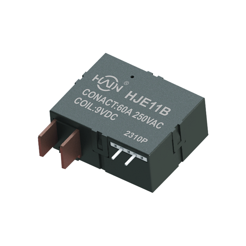
Product Definition: This product is a high-performance relay designed specifically for multi-user smart meters, aiming to solve the performance and energy consumption challenges in centralized meterin...
See Details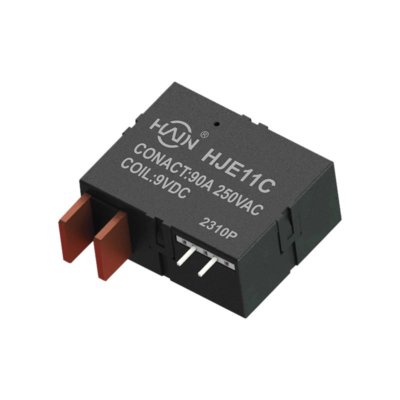
Product Overview: A Reliable "Power Steward" in Smart Metering In complex scenarios involving multiple users sharing electricity, power distribution safety and precise control are paramount. The HJE11...
See Details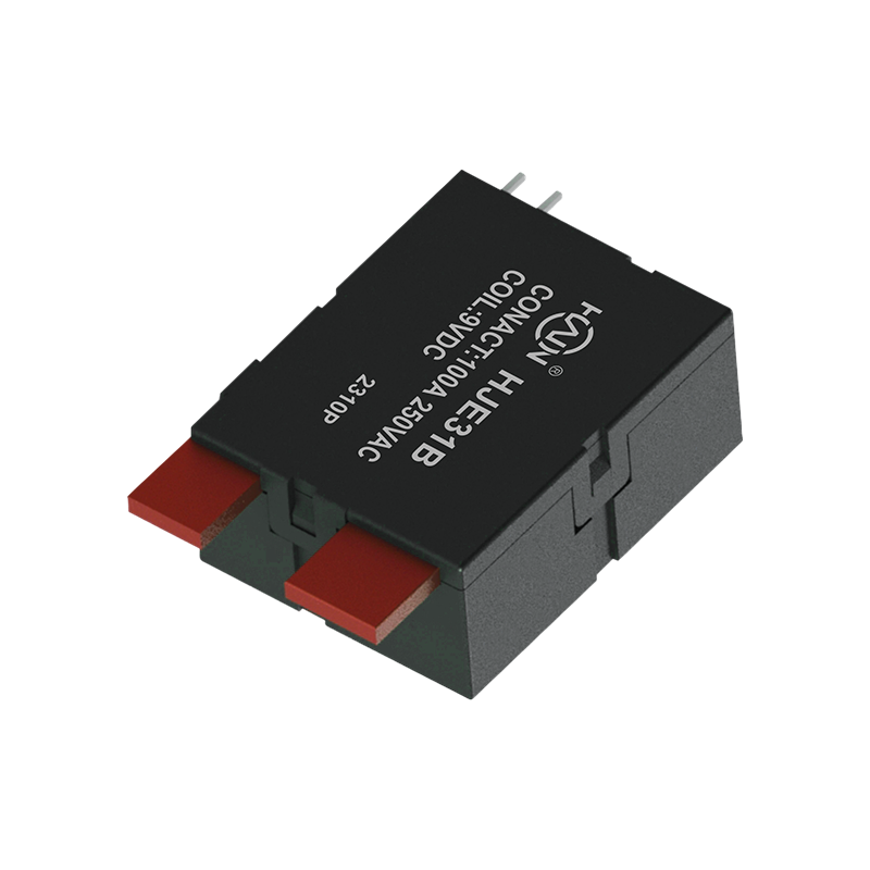
Product Definition: The HJE31B 80A is a relay specifically designed for multi-user electricity metering systems. Utilizing advanced magnetic latching technology, it maintains its operational state eve...
See Details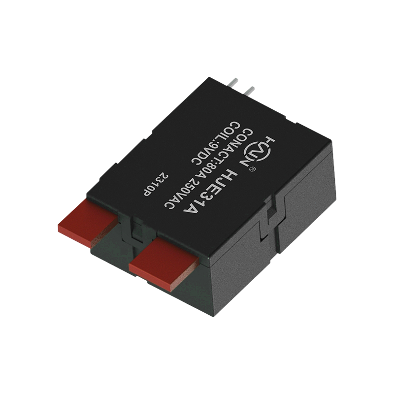
HJE31A 60A – A Reliable Guardian for Multi-User Smart Metering In multi-user centralized power supply systems, safe and stable load control is crucial for ensuring fair and safe electricity use. The H...
See Details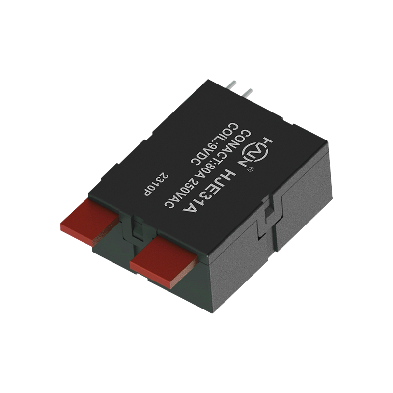
Product Definition: A bottom-in, bottom-out relay specifically designed for 2P DIN rail meters, aiming to improve installation efficiency and system reliability through optimized wiring structure.
See Details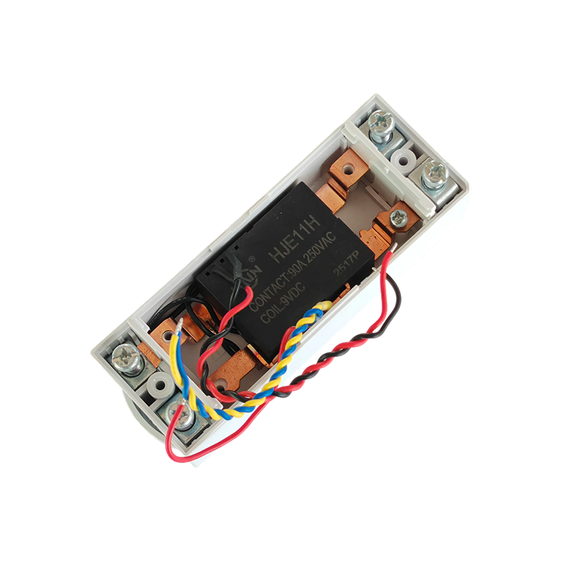
Product Definition:This product is a top-in, bottom-out 2-pole DIN rail relay designed specifically for modern power distribution systems. It integrates a 90A high current carrying capacity, compact s...
See Details
 Add.
Add.
|
No. 707, Yanyu Road, Yucheng Town, Haiyan County, Jiaxing City, Zhejiang Province, China
|
 Phone
Phone
|
+86-188-5739-7300
|
 Email.
|
alio@hj-relay.com
|
Copyright @ Huajin Technology Jiaxing Co., Ltd. All rights reserved.

