



 English
 中文简体
 русский
NEWS
 Home / News / Industry News / Relay for AC Charging Station: Latching Relay Selection Guide for 7 to 22 kW Posts Home / News / Industry News / Relay for AC Charging Station: Latching Relay Selection Guide for 7 to 22 kW Posts
Content
A relay for an AC charging station is a bistable switch rated at 250 VAC that makes and breaks the mains supply to the vehicle socket, and it holds its last position without coil current. Inside an IEC 61851-1 Mode 3 post the relay sits downstream of the energy meter and upstream of the socket, so every kilowatt-hour billed passes through its contacts.
Definition: a magnetic latching relay keeps its contact position with a permanent magnet. A coil pulse of 50 ms to 100 ms flips the armature, and the state survives the loss of coil power. The device works as a mechanical memory element as well as a switch.
That memory is why the part matters in metering equipment. A post must stop billing when a session ends, isolate the socket before a user unplugs under load, and keep the open or closed state predictable after a supply interruption. One latching contact answers all three requirements.
A latching relay removes continuous coil dissipation and keeps its state through a mains loss. The trade-off is control logic that must know and drive two stable states instead of one.
State memory is both the advantage and the risk. After a control-side failure a latching relay stays closed, so the safety chain needs a hardware path that forces the reset coil, plus a contact-state read-back or a defined power-on routine. Teams migrating from a contactor usually underestimate this part of the change.
Design check: fix three numbers before layout freeze. The minimum pulse width at the lowest specified coil voltage, the maximum coil temperature rise at 85 degrees Celsius ambient, and the guaranteed reset behaviour at power-on. A 120 A latching relay that cannot be reset reliably at low ambient becomes a warranty claim.
A 22 kW three-phase AC post draws 32 A per phase, while the 250 VAC latching platforms listed for charging and metering duty run from 60 A to 150 A, so a 120 A model leaves more than three times headroom over the nominal phase current. Huajin lists separate AC and DC charging station relay families, and the AC range is built around PDU load switching at 250 VAC.
| Contact rating | Rated voltage | Example model | Typical AC post class |
| 60 A | 250 VAC | HJE11B60A | 3.7 kW to 7 kW, single-phase |
| 90 A | 250 VAC | HJE11C90A | 7 kW to 11 kW |
| 100 A | 250 VAC | HJE11D100A | 11 kW |
| 120 A | 250 VAC | HJE11F120A, HJE12A120A | 22 kW three-phase with derating headroom |
| 150 A | 250 VAC | HJE12A150A | 22 kW three-phase at high internal ambient |
The HJE11F120A is catalogued as a 120 A, 250 VAC latching relay for PDU duty, and the HJE12A120A shares that rating with a different contact and coil arrangement. Both are single-phase devices, so a three-phase post uses one per pole or a multi-pole assembly inside the same housing.
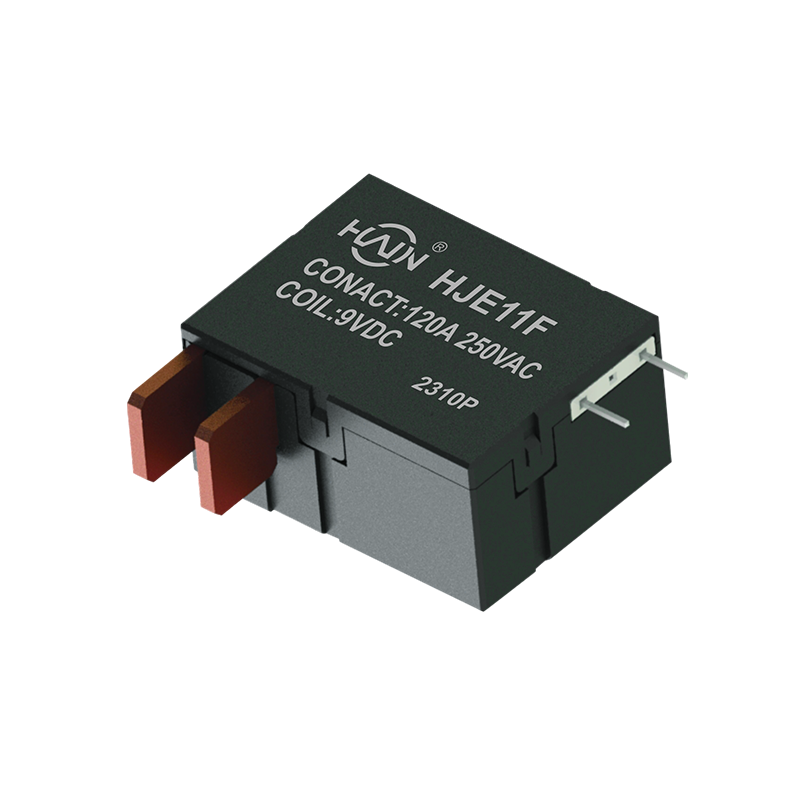 HJE11F/HJE12A 120 A Latching Relays for PDU Duty120 A, 250 VAC single-phase PCB latching relays for PDU poles; check temperature derating curves before selecting ratings for sealed enclosures.View Product →
Derating is where most specifications go wrong. Usable current inside a sealed post falls well below the catalogue figure once internal ambient passes 60 degrees Celsius, so request the temperature derating curve and confirm the chosen rating at the real enclosure temperature, not at 25 degrees Celsius bench conditions.
Six checks separate a relay that survives ten years in the field from one that welds its contacts in month eight: load profile, ambient derating, coil drive window, dielectric clearance, contact material, and documented life test data.
A charging relay is qualified on IEC 61810-1 and applied inside an EVSE built to IEC 61851-1, while GB/T 18487.1 governs the charging system in China. A quotation package should name all three, plus IEC 60664-1 for the clearance and creepage calculation.
Capacity is rarely the constraint in this product category; consistency is. Huajin, founded in May 2021 and based in Haiyan, Zhejiang, runs an 8,000 square metre plant with more than 120 staff and an annual output above 10 million magnetic latching relays, roughly 30 per cent of which is exported.
For an AC charging programme the useful question is how far the supplier will move on customization: coil voltage, contact plating, terminal geometry, housing height, and the wiring harness that mates with the PDU. A relay that fits the existing footprint without a bracket redesign saves more engineering time than a marginally lower unit price.
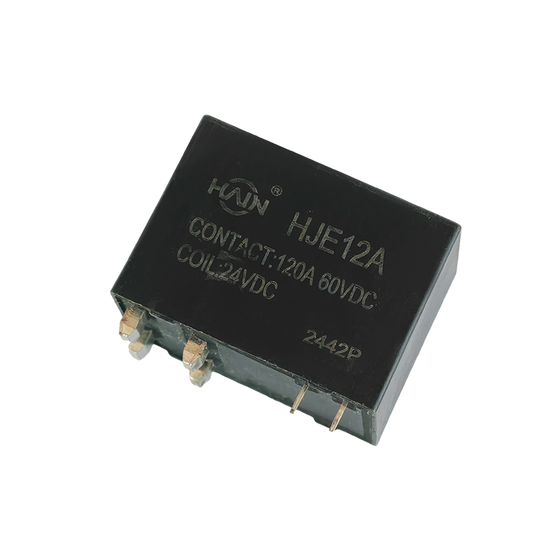 HJE12A 120 A PCB Latching Relay for PDUsThrough-hole 120 A, 250 VAC relay for compact high-density PDUs; suitable when footprint and coil or terminal customization matter for charging programmes.View Product →
The same latching platform is reused across metering, protection and charging categories, which is why customization work stays short: the contact system is already validated, and the change is usually mechanical or coil-related. For special coil voltages, dual-coil control or modified terminals, the custom magnetic latching relay programme covers samples and tooling.
Verification checklist for a first order: request the derating curve, the endurance report, the coil drive specification with tolerance band, and a batch of production samples for a 500-cycle load test in your own enclosure before releasing volume.
A 22 kW post draws 32 A per phase at 230 V phase-to-neutral, so a 120 A, 250 VAC latching relay such as the HJE11F120A gives more than three times headroom for ambient derating, inrush and long-term contact wear.
Metered AC posts favour magnetic latching relays because the contact holds state with zero coil current, which removes continuous coil heat from a sealed enclosure and preserves the open or closed position through a mains interruption.
Service life is limited by electrical endurance rather than mechanical operations. A post running two switching cycles per day accumulates about 7,300 cycles over ten years, so an endurance rating at rated current is the figure to compare, not the headline mechanical count.
State contact rating at 250 VAC, number of poles, coil voltage and pulse width, ambient temperature inside the enclosure, terminal type, expected switching cycles per year, and the standards the post will be certified against, so the supplier can propose a matching latching relay instead of a generic catalogue part.
Product Overview: Designed specifically for high-density power distribution units (PDUs), this high-power control core is directly integrated into the PCB board. With a robust 120A/250VAC load capacit...
See Details
The Powerful Core of the PDU! The HJE12A-120A is a PCB-based through-hole high-power relay designed specifically for rack-mount power distribution units (PDUs), aiming to achieve PDU miniaturization, ...
See Details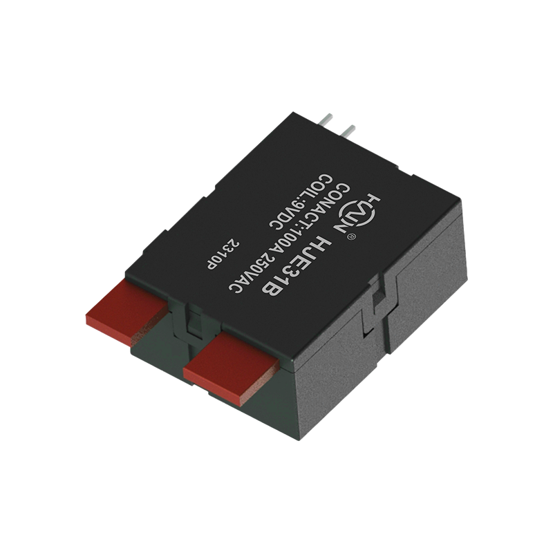
Product Definition: The HJE31B-100A is a split-type 7P DIN rail relay designed specifically for three-phase power systems. It features current monitoring, relay protection, and energy metering functio...
See Details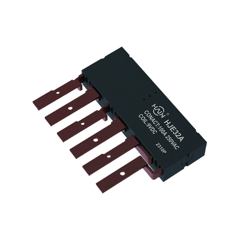
Product Definition: The HJE32A-100A is an innovative integrated three-phase relay designed specifically for 7P DIN rail meters. It aims to perfectly integrate three-phase metering and control, signifi...
See Details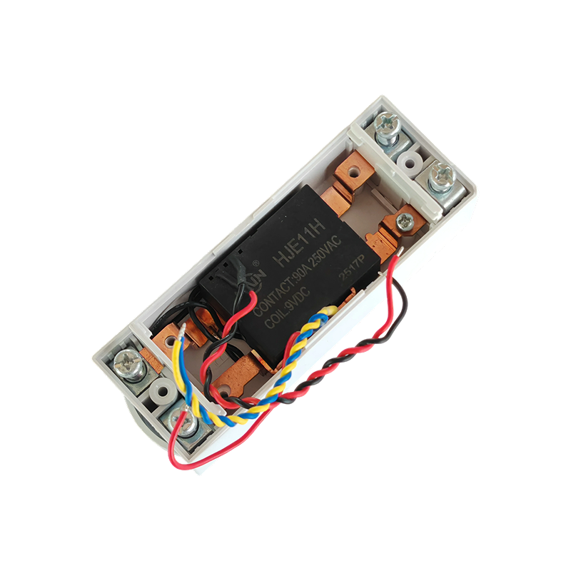
Product Definition:This product is a top-in, bottom-out 2-pole DIN rail relay designed specifically for modern power distribution systems. It integrates a 90A high current carrying capacity, compact s...
See Details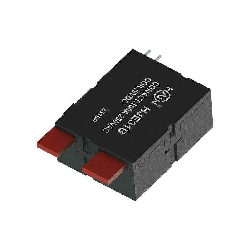
Product Definition: The HJE31B 80A is a relay specifically designed for multi-user electricity metering systems. Utilizing advanced magnetic latching technology, it maintains its operational state eve...
See Details
 Add. |
No. 707, Yanyu Road, Yucheng Town, Haiyan County, Jiaxing City, Zhejiang Province, China
|
 Phone |
+86-188-5739-7300
|
 Email. |
alio@hj-relay.com
|
Copyright @ Huajin Technology Jiaxing Co., Ltd. All rights reserved.
