



 English
 中文简体
中文简体 русский
NEWS
 Home / News / Industry News / DIN Rail Meter Relay Selection Guide: Current Ratings, Pole Counts, and Sourcing Risks Home / News / Industry News / DIN Rail Meter Relay Selection Guide: Current Ratings, Pole Counts, and Sourcing Risks
Content
That imbalance is worth correcting. The relay inside a DIN rail meter is not a generic switch. It sits between the metering front end and the load terminals, it has to hold a position for years without continuous coil current, and it has to survive inrush events that the meter's own current transformer never sees. Specify the wrong device and the failure mode shows up later as welded contacts, discoloured terminal blocks, or a meter that refuses to drop the load during a tamper event.
What follows covers what a DIN rail meter relay actually does, how to match current rating and pole count to a 2P, 4P, or 7P meter body, and where the real sourcing risk sits for engineers and procurement teams building a metering platform.
A DIN rail meter relay is a bistable latching switch that connects or isolates the load circuit of a DIN rail mounted electricity meter, then holds its last position with zero continuous coil current.
Three properties follow from that design, and each one changes how a meter behaves once it is installed on a wall.
A latching relay uses a permanent magnet to hold its armature in the last switched state. A brief current pulse through the set or reset coil moves the armature; once it has moved, no coil current is needed to keep it there.
The contrast with a conventional electromagnetic relay is worth stating plainly. A non-latching relay must stay energized for as long as the load remains connected. In a 100 A meter that means a coil drawing one to three watts continuously, which becomes heat inside a sealed DIN enclosure and a permanent deduction from the meter's own accuracy budget.
Size the relay at 1.25 to 1.5 times the meter's nominal current, and take the pole configuration from the meter housing rather than from the wiring diagram.
A DIN rail meter is built around a fixed terminal layout. A 4P body carries three phase conductors plus neutral, and the relay has to fit the space left behind by the terminal block and the current transformer. A 7P body spreads the same measurement across more channels, and the relay package shifts from a single moulded block to either a split arrangement or an integrated unit with the shunt or CT already mounted on it.
| Meter form | Relay configuration | Typical current | Integration detail |
| 2P DIN rail | Compact latching relay | 80 to 100 A | External shunt or shunt CT |
| 4P DIN rail | Single latching relay | 60 to 100 A | Shunt CT mounted on the relay body |
| 7P DIN rail | Split or integrated multi-unit | 80 to 100 A | CT integrated into the relay housing |
| Dual-circuit meter | Dual-channel latching relay | 60 to 100 A | UC2 or UC3 compliant channel layout |
| Multi-user panel | Multi-circuit split relay | 60 to 80 A | Separate contact sets per metering channel |
That heat estimate is not a theoretical exercise. A relay rated for 100 A with 1 mΩ of contact resistance converts 10 W into the interior of a meter that may have no active cooling at all. Halving that resistance to 0.5 mΩ drops the dissipation to 5 W and doubles the thermal headroom available to the rest of the design.
Count the circuits that must switch independently before you count amperes, because the number of isolated contact sets decides the package long before the current rating does.
A single-phase DIN rail meter normally needs one latching contact set, but the physical package is decided by whether the meter uses a discrete shunt or a shunt CT. A 4P DIN rail body with a shunt CT on board needs a relay whose terminals align with the CT secondary rather than with a separate busbar. Getting that alignment wrong is the single most common reason a first prototype will not close.
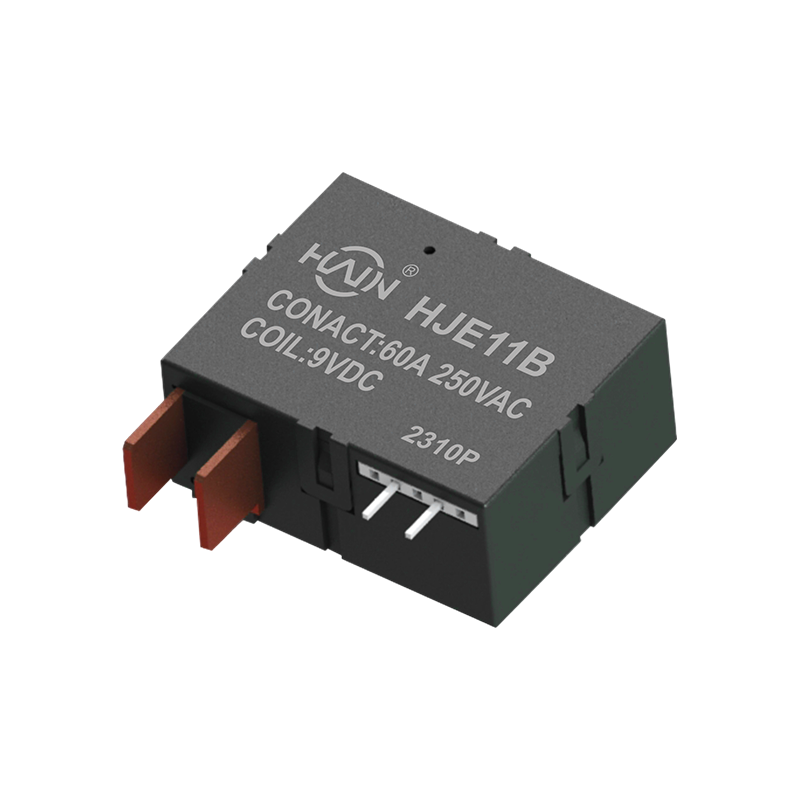 HJE11B-60A Latching Relay with Shunt/CT for 4P DIN Rail MeterCombines 60 A switching and power metering in a DIN rail 4P format, with terminals aligned to the on-board shunt CT for meter integration.View Product →
Three-phase metering pushes the relay into either a split arrangement, where the contact block and the CT sit in separate housings, or a fully integrated unit. Split designs ease assembly and serviceability but add a busbar connection that must carry full load current. Integrated designs remove that joint but demand tighter moulding tolerances and a larger tooling investment up front.
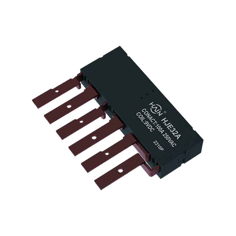 HJE32A-100A Integrated Latching Relay with Shunt/CT for 7P DIN Rail MeterIntegrates three independent relay functions for 7P DIN rail three-phase metering, with 100 A switching and a compact integrated housing.View Product →
Dual-channel and multi-circuit meters place several independent contact sets inside one device, which turns the relay into a small switchgear assembly. Current per channel typically drops into the 60 to 80 A band, but channel-to-channel isolation, creepage distance, and the mechanical keying that prevents a channel from being swapped during assembly all become engineering requirements rather than catalogue options.
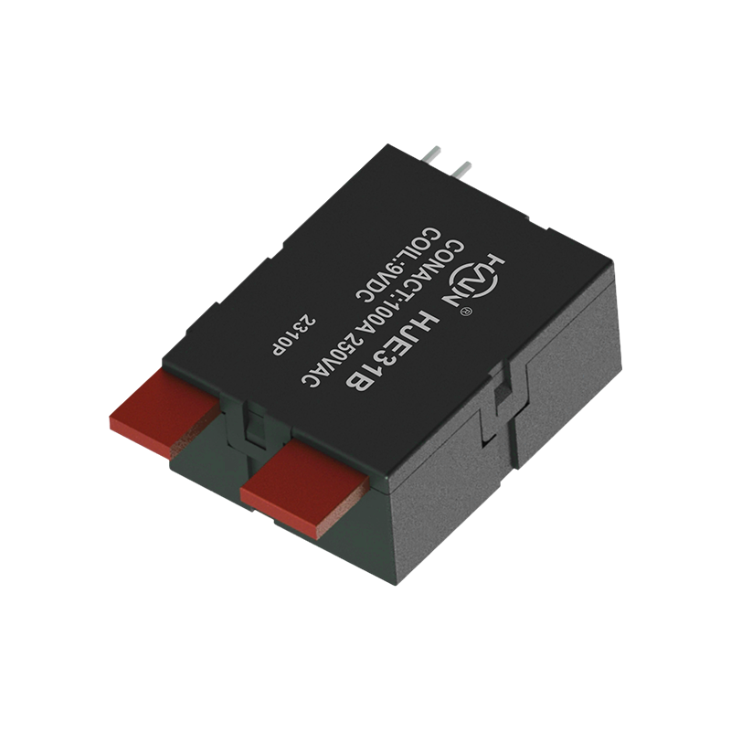 HJE31B-100A Split-Type Latching Relay for Multi-Functional Power SystemsSplit-type 100 A relay combines protection, current monitoring, and energy metering for DIN rail multi-functional power systems.View Product →
Huajin Technology Jiaxing Co., Ltd., which manufactures this range, organises its DIN rail relay catalogue along exactly these topology lines. A cross-check against the published selection reference for DIN rail meter relay types and selection confirms the same split between single-phase, dual-circuit, three-phase, and multi-circuit families.
Latching relays dominate DIN rail metering because they remove the coil from the continuous thermal load, and that single change buys back accuracy, enclosure space, and service life at the same time.
Across the DIN rail meter relays catalogued by Huajin Technology Jiaxing Co., Ltd., the 100 A class is the centre of gravity of the range. The distribution below counts catalogue entries per current rating and shows how strongly the 100 A band dominates.
The concentration around 100 A is not an accident of catalogue design. Most DIN rail meters sold into commercial and light industrial distribution boards sit between 80 A and 120 A per phase, so relay makers build their tooling around that band and treat 60 A and 150 A as edge products for specific utility specifications.
Work through these six checks in order, because each one eliminates a class of relay that will not fit the platform regardless of how good its datasheet looks.
A relay that latches reliably at 40 ms and releases cleanly at 250 VAC costs the same as one that does not. The difference is entirely in the magnetic circuit design and the contact material specification.
Certification coverage, not unit price, is the variable that most often decides whether a metering programme survives first article inspection.
Scale matters here as well. A supplier producing ten million latching relays a year can absorb the cost of a dedicated mould for a 7P variant, while a trading operation reselling imported stock cannot. For a meter platform expected to run for five to eight years, that manufacturing depth is what keeps the second and third production batches identical to the first.
A DIN rail meter relay is magnetically latching, so it holds its last switched state without continuous coil current. A standard power relay needs the coil energized for the entire time the load is connected, which adds continuous heat and standby consumption inside the meter enclosure.
Start at 1.25 to 1.5 times the meter's nominal current. For a 60 A meter that lands on an 80 A relay, and for an 80 A meter it lands on the 100 A class, which is also the most widely tooled rating in the DIN rail family.
No. A set or reset pulse of roughly 10 to 50 ms is enough to move the armature, and the permanent magnet holds it afterwards. This is why meter designers can drive the coil directly from a microcontroller pin through a small MOSFET.
Look for a certified quality management system at company level, plus product level approvals covering the specific relay family you are buying. Utility metering programmes frequently add their own requirements on top, so confirm that the exact model has been approved for the standard your meter must meet.
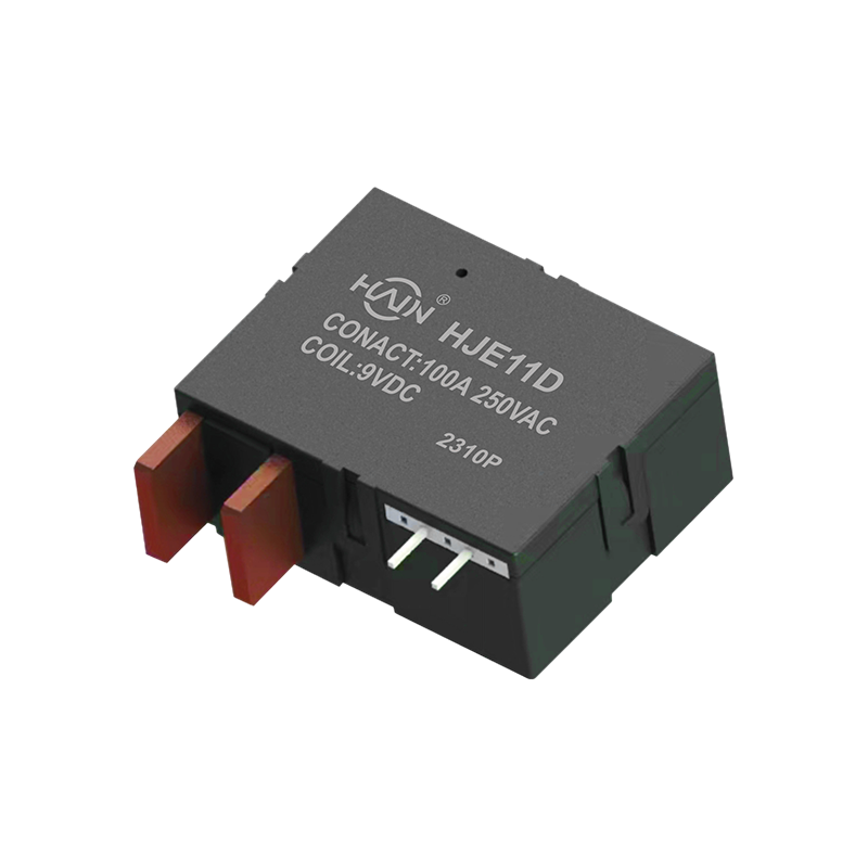
Redefining the DIN rail meter, one chip solves two major problems! The HJE11D-100A is a high-current relay with metering function designed specifically for 4P DIN rail energy meters. It aims to solve ...
See Details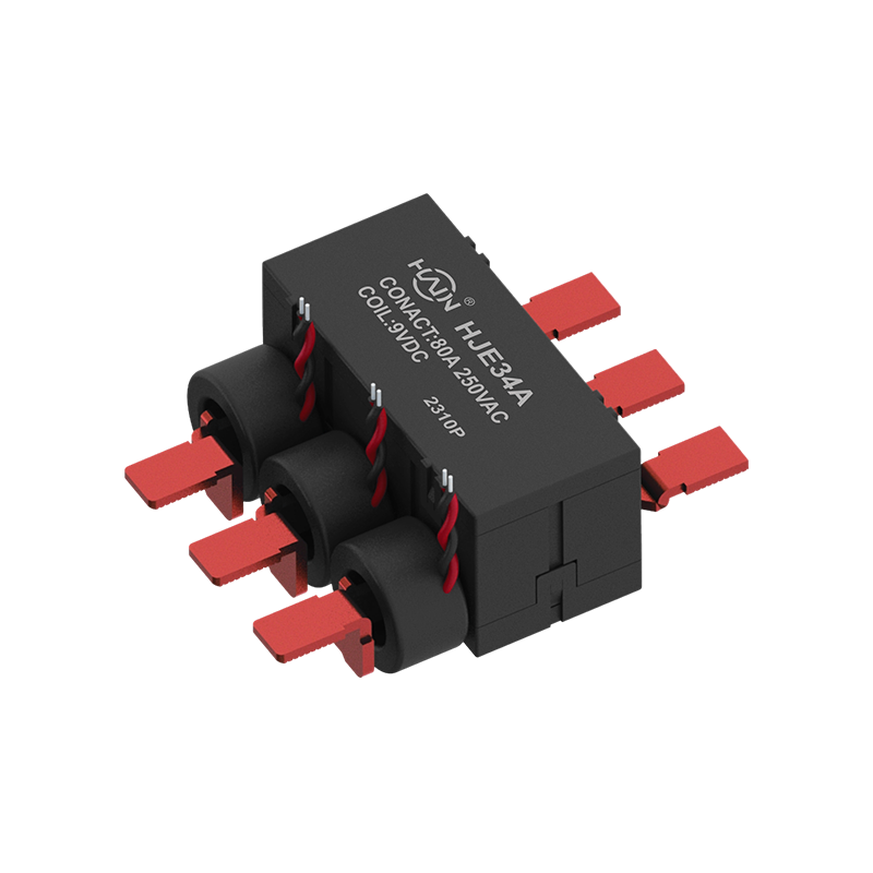
A Revolution in Integrated Three-Phase Power Control This is a highly integrated 4-pole three-phase rail relay, designed specifically for intelligent control and power distribution protection of three...
See Details
Product Definition: The HJE32A-100A is an innovative integrated three-phase relay designed specifically for 7P DIN rail meters. It aims to perfectly integrate three-phase metering and control, signifi...
See Details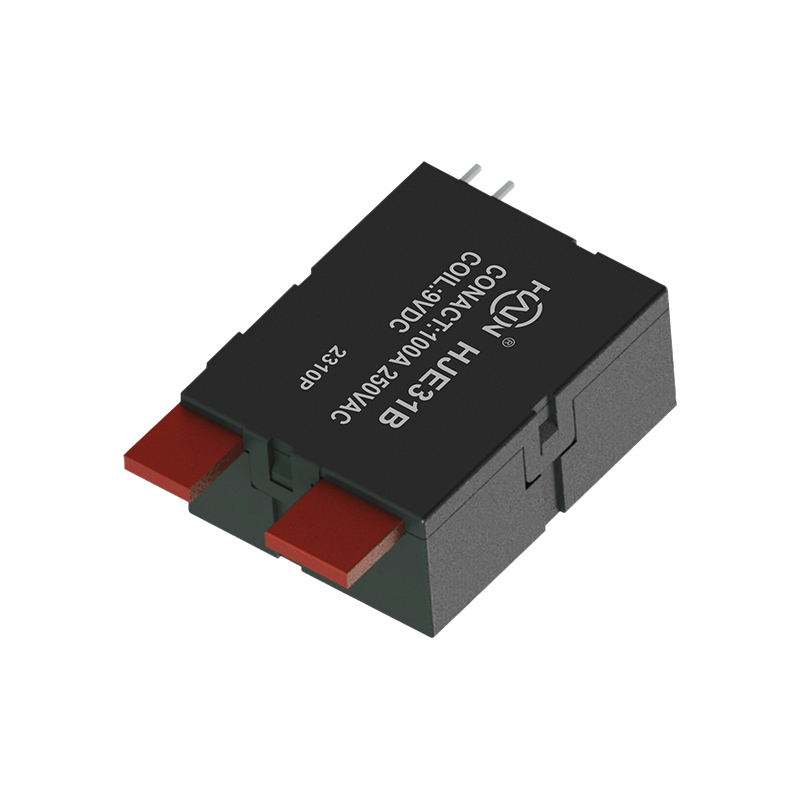
Product Definition: The HJE31B-100A is a split-type 7P DIN rail relay designed specifically for three-phase power systems. It features current monitoring, relay protection, and energy metering functio...
See Details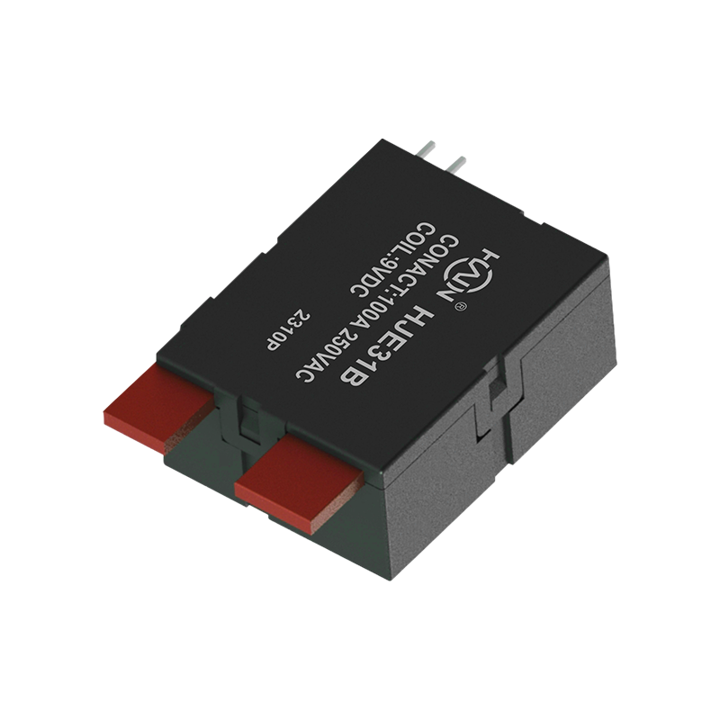
Product Definition: The HJE31B-100A is a two-pole rail relay specifically designed for high-current energy metering systems. It utilizes advanced technology to achieve efficient current detection and ...
See Details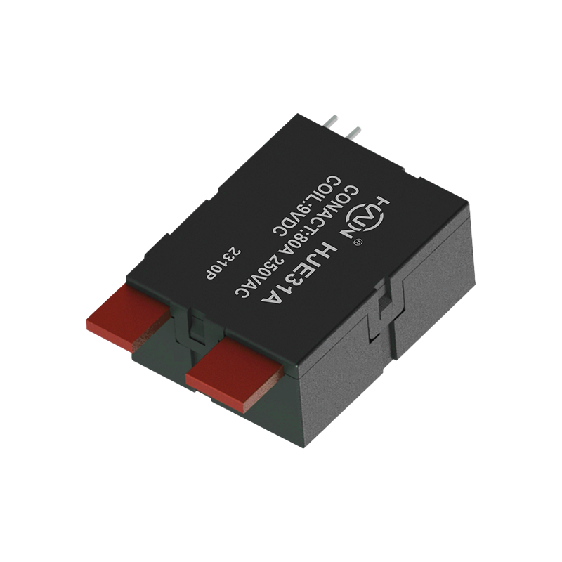
Product Definition: A bottom-in, bottom-out relay specifically designed for 2P DIN rail meters, aiming to improve installation efficiency and system reliability through optimized wiring structure.
See Details
 Add.
Add.
|
No. 707, Yanyu Road, Yucheng Town, Haiyan County, Jiaxing City, Zhejiang Province, China
|
 Phone
Phone
|
+86-188-5739-7300
|
 Email.
|
alio@hj-relay.com
|
Copyright @ Huajin Technology Jiaxing Co., Ltd. All rights reserved.
