



 English
 中文简体
中文简体 русский
NEWS
 Home / News / Industry News / Energy Meter Relay Selection Guide: Current Ratings, UC2 vs UC3 and Meter Formats Home / News / Industry News / Energy Meter Relay Selection Guide: Current Ratings, UC2 vs UC3 and Meter Formats
Content
A meter engineer finalising a 100A single-phase smart meter spends more design time on the energy meter relay than on almost any other part of the bill of materials. That relay carries the full service current, has to hold its last position for years without coil power, and must clear impulse and temperature rise tests that have nothing to do with its nameplate rating. Huajin Technology Jiaxing Co., Ltd. manufactures exactly this class of component in Haiyan County, Zhejiang: magnetic latching relays from 60A to 150A at 250VAC, built at a capacity above 10 million units a year.
An energy meter relay is a magnetically latching switch that opens or closes the meter load circuit and then holds that position with no coil current. That single property separates it from a general purpose power relay, and it is the reason a meter can meet its own consumption and accuracy limits.
A conventional relay needs continuous coil power to stay energised. A 100 mW coil held closed for a year draws roughly 0.88 kWh, all of it taken from the meter internal supply and dissipated as heat inside a sealed enclosure. A latching relay is driven by a short pulse, usually tens of milliseconds long, after which a permanent magnet holds the armature in place. Holding power falls to zero, and the meter supply only has to deliver a brief, repeatable burst of energy.
An energy meter relay is a bistable electromechanical switch rated for the meter full service current, used to connect and disconnect the load and to hold its last commanded state without continuous coil excitation.
Four characteristics decide whether a latching relay survives a ten year meter life:
Contact current rating is the first filter in energy meter relay selection, because it is fixed by the meter service class rather than by the preference of the design team. A 60A relay placed in a 100A direct connect meter will fail on temperature rise long before it fails mechanically.
Direct connect residential meters in most markets sit between 60A and 80A. Markets with heavy domestic loads push to 100A, and light commercial sites with on site EV charging reach 120A to 150A on a single phase. Three phase meters typically specify 100A to 120A per phase, which is why the three phase latching range stops at 120A.
Nameplate current alone is not enough. Continuous carry capability falls as ambient temperature rises, and the interior of a sealed polycarbonate meter can run 20 to 30 degrees above outdoor temperature. A part that carries 100A at room temperature may need a larger contact system to carry the same current at 70 degrees Celsius. Ask for the temperature rise curve, not just the headline number. A companion guide covers energy meter relay selection by current class and standard in more depth.
Maximum contact current available per application family (A)
The physical format of an energy meter relay follows the meter housing, not the electrical rating. The same 100A switching element is frequently supplied as a split unit, an integrated unit with a shunt CT, or a vertical body version, and only one of those will fit a given enclosure. The DIN rail meter relay range is catalogued exactly this way, by pole count and by mounting pattern.
The distinction matters at the assembly stage. A split type relay mounts beside the current path, while an integrated type carries the shunt CT inside the relay body and removes one soldered joint from the meter current circuit. Fewer joints means less contact resistance drift and a shorter production line.
| Meter platform | Relay format | Typical current | Example model |
| Wall mounted, single phase | Standard latching | 60-150 A | HJE11F120A, UC3 |
| Wall mounted, dual channel | Two channel latching | 60-100 A per channel | HJE24A100A, UC3 |
| Multi user meter | Multi circuit latching | 60-90 A | HJE11B-60A |
| Three phase meter | Three phase latching | 100-120 A | HJE33D120A, 25th edition |
| 2P DIN rail | With shunt or shunt CT | 80-100 A | HJE31B100A |
| 4P DIN rail | With shunt CT | 60-100 A | HJE11C90A |
| 7P DIN rail | Split or integrated CT | 100 A | HJE32A100A |
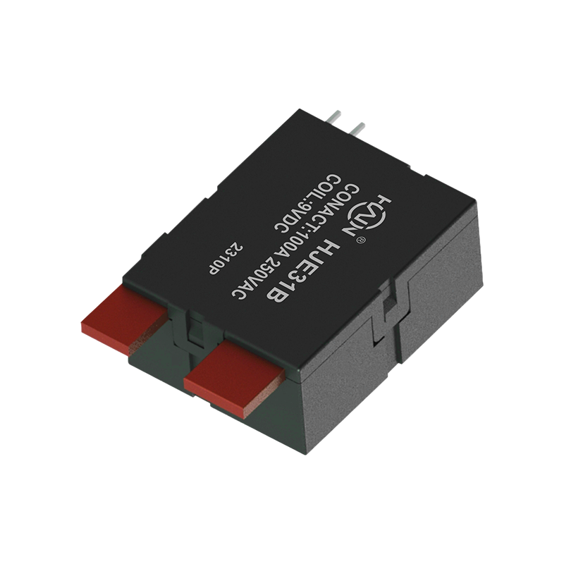 HJE31B-100A UC2 Latching Relay for 2P DIN Rail MetersA 100A two-pole DIN-rail latching relay for high-current energy meters, IEC 62055-31 UC2 compliant and suited to 60-100A UC2 metering applications.View Product →
UC2 and UC3 are switching device classes defined for payment meters in IEC 62055-31, and the class determines how much switching endurance and current duty a relay has to survive. UC3 covers the heavier duty, so UC3 parts are normally specified at 120A and above, while UC2 parts sit in the 60A to 100A band.
Two relays carrying an identical 100A nameplate can differ by an order of magnitude in switching endurance. The UC class is where that difference is written down.
Chinese grid tenders add a second layer. The State Grid 25th edition specification tightened requirements for meter switching devices, and the catalogue lists both single phase and three phase relays built to that edition. For a utility project, certification evidence carries as much weight as the data sheet: ISO 9001-2015 for the quality system, plus CCC, State Grid and TUV approvals on the product itself. A supplier that already holds those marks removes weeks from a tender qualification cycle.
The same latching platform that switches a meter load also disconnects EV charging current, protects against overvoltage and undervoltage, and switches capacitor banks. All four duties need high current, a bistable state and near zero holding power, so they pull from one product family.
DC charging is the clearest example of a different voltage envelope. The AC side of a charging pile uses 250VAC latching relays at 120A inside the power distribution unit, while the DC side switches 48VDC at 150A. Reusing a 250VAC meter relay on a 48VDC DC bus is a mistake, and the naming convention on this DC charging latching relay makes the boundary explicit.
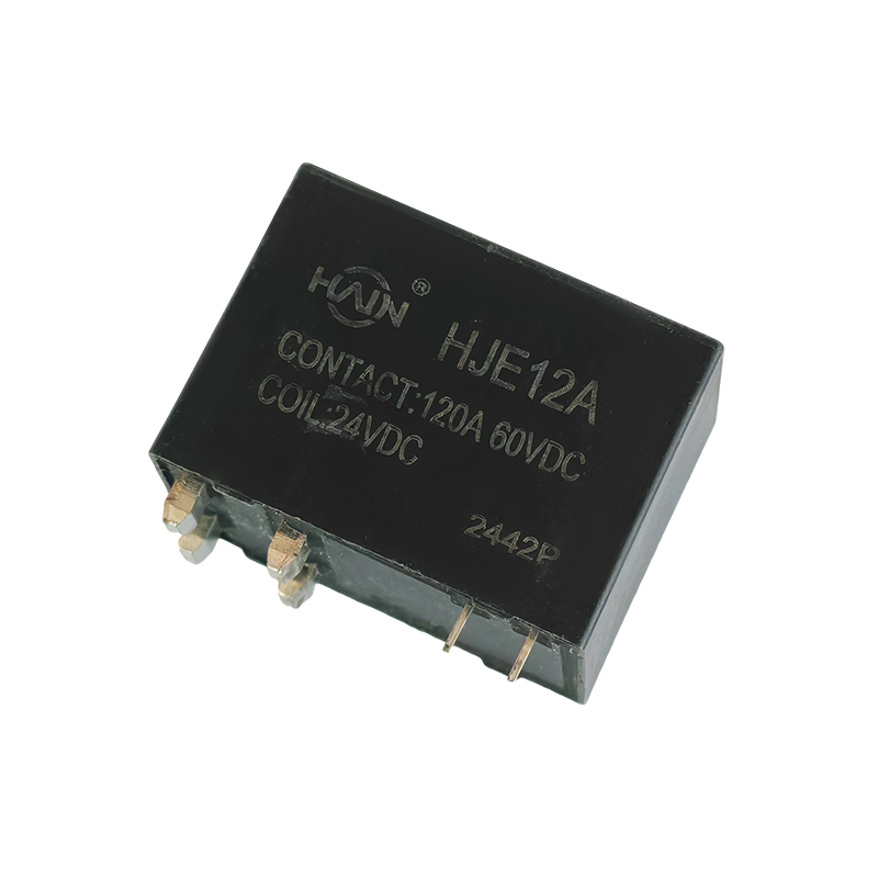 HJE12A-150A-48VDC Latching Relay for DC ChargingA 150A 48VDC latching relay for DC charging, with double contacts, magnetic blowout, and an auxiliary switch for status checking.View Product →
Shared platforms cut qualification effort. Once a contact system has passed temperature rise and endurance testing in a metering application, the same body can usually be re-qualified for a protector or a capacitor switch with far less test time.
Approving a relay sample is a sequence, not a single bench test. Working through these six checks in order prevents the common failure of validating a part that cannot be produced in the required format.
It connects and disconnects the load circuit inside an electricity meter and holds its last commanded state without coil current. The same device family also switches charging current, trips overvoltage and undervoltage protectors and operates smart capacitor banks.
Both are switching device classes from IEC 62055-31 for payment meters. UC3 carries the heavier switching duty and higher current duty, so UC3 parts are specified from 120A upward, while UC2 parts cover the 60A to 100A band.
Yes. A 60A 250VAC body appears in overvoltage protector, undervoltage protector, three phase smart capacitor and multi circuit meter catalogues. Reuse shortens qualification because the contact system has already passed the same endurance tests.
Let the enclosure decide. Wall mounted meters accept standard single phase, dual channel and three phase bodies, while DIN rail meters constrain the relay to 2P, 4P or 7P module widths and often require an integrated shunt or shunt CT.
Relay selection ends where a data sheet begins: on the test bench, at 70 degrees ambient, with a pulse drive taken from the meter's own supply. A part that passes there will still be switching load current a decade after the meter leaves the line.
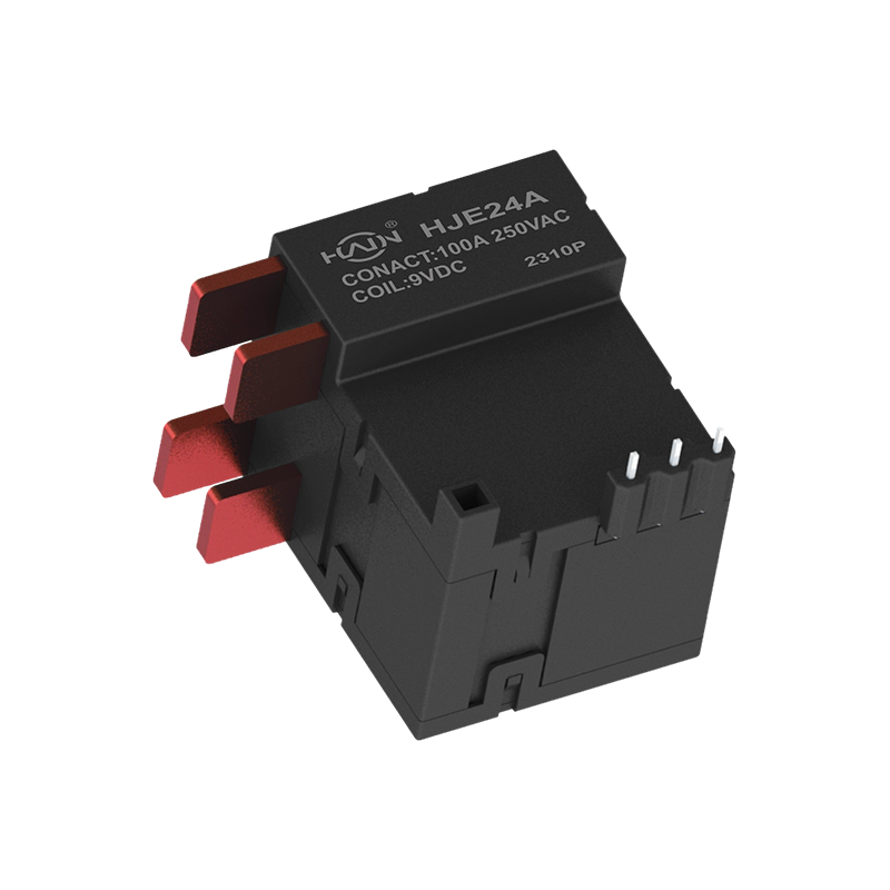
Product Definition: This product is a dual-channel high-power magnetic latching relay conforming to the stringent UC3 standard, designed specifically for high-safety, high-efficiency energy control sc...
See Details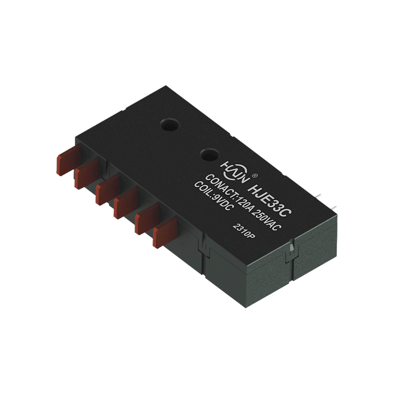
In industrial scenarios requiring reliable control of three-phase high-power loads, this product is a strategic choice for improving system energy efficiency and reliability. It not only meets the hig...
See Details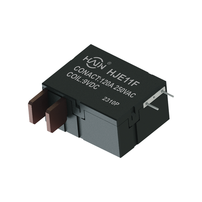
Product Definition: This product is a single-phase magnetic latching relay designed for high-power power control scenarios. It employs an energy-saving magnetic latching structure, possessing high cur...
See Details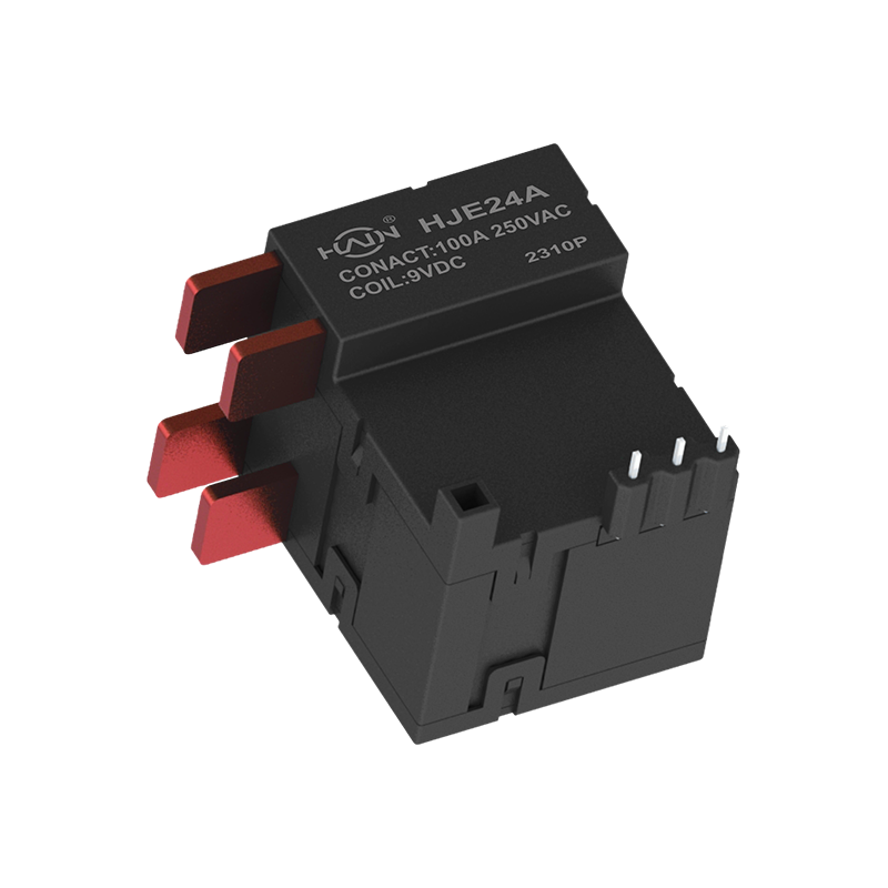
Dual-core drive, designed for demanding power control This is a high-current dual-channel relay compliant with UC3 safety standards, specifically designed for industrial scenarios requiring independen...
See Details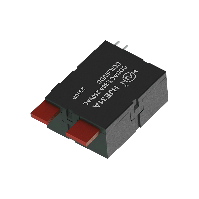
Product Definition: A bottom-in, bottom-out relay specifically designed for 2P DIN rail meters, aiming to improve installation efficiency and system reliability through optimized wiring structure.
See Details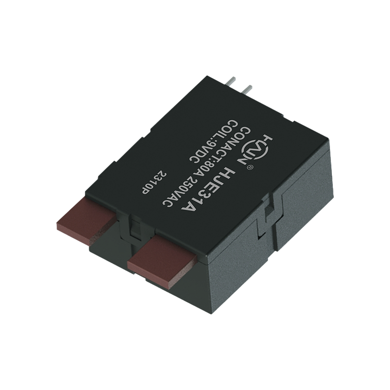
This product utilizes magnetic latching bistable technology, making it an energy-saving power control component. It consumes energy only momentarily when the coil is pulse-driven; once the state switc...
See Details
 Add.
Add.
|
No. 707, Yanyu Road, Yucheng Town, Haiyan County, Jiaxing City, Zhejiang Province, China
|
 Phone
Phone
|
+86-188-5739-7300
|
 Email.
|
alio@hj-relay.com
|
Copyright @ Huajin Technology Jiaxing Co., Ltd. All rights reserved.
