



 English
 中文简体
中文简体 русский
NEWS
 Home / News / Industry News / Energy Meter Relay Selection: Current Ratings, Standards, and Application Fit Home / News / Industry News / Energy Meter Relay Selection: Current Ratings, Standards, and Application Fit
A smart meter that cannot disconnect the load on command is more than a metering fault; it is a revenue and safety risk. The energy meter relay is the electromechanical component that physically separates the meter from the supply when a remote disconnect command arrives, and in most designs it is a magnetic latching relay rated for 60 A to 150 A of continuous current. When the relay is mis-specified, the problems surface later: welded contacts during surge events, relays that change state when a strong external magnet is applied, or coils that draw more current than the meter's driver stage can supply.
In a typical single-phase meter, two relays are used: one in the live line and one in the neutral path. That arrangement doubles the switching burden on the meter's control electronics, which is why the relay's coil drive requirements and contact performance must be treated as part of the meter design, not as a catalog afterthought.
Magnetic latching relays hold their contact position without continuous coil power. A short pulse changes the state, and the relay stays there until the next pulse. That behavior is what makes remote disconnect and reconnect economical in battery-backed or low-power meter designs. Our technical note on high-reliability control for smart meters covers the control side of this duty in more detail.
Before evaluating a relay, fix the electrical boundary conditions of your meter. The most important parameters are continuous current, rated voltage, coil voltage, contact arrangement, and expected mechanical endurance. Utilities rarely describe these in the datasheet language of relay manufacturers, so it is common for a meter engineer to translate a tender requirement into an actual relay specification.
| Parameter | Typical range | Design impact |
|---|---|---|
| Continuous current | 60 A - 150 A | Sets the meter class and thermal budget |
| Rated voltage | 250 VAC; 48 VDC for DC charging | Determines clearance, creepage, and arc behavior |
| Coil voltage | 6 VDC - 24 VDC | Must match the meter power supply and driver transistor |
| Contact arrangement | 1-pole, 2-pole, 3-pole | Matches single-phase, dual-circuit, or three-phase architecture |
| Mechanical endurance | 10,000 - 100,000 operations | Limits meter service life expectations |
| Anti-magnetic capability | Resists external magnetic field interference | Prevents tampering and false state changes |
The continuous current rating must cover not only the meter's nominal load but also short-duration overloads that occur during fault clearing or motor starts in the customer installation. A 60 A relay in a meter rated for 60 A service often leaves little margin; 80 A, 90 A, and 100 A variants are common choices when the utility expects sustained loading close to the meter's nameplate rating.
Voltage rating is usually 250 VAC for wall-mounted and DIN rail meters. DC charging applications are different: a DC charging post may require a relay rated at 48 VDC with a higher DC current capability, because DC arcing behaves differently from AC arcing and the contact gap must be sized accordingly.
Contact configuration follows the meter topology. A single-phase meter uses a single-pole relay, or two single-pole relays for live and neutral disconnection. Dual-circuit meters use a two-channel relay or two independent relays. Three-phase meters use three-pole or four-pole devices with enough contact spread to interrupt all phases together.
On the coil side, single-coil latching relays change state by reversing the polarity of the drive pulse; two-coil versions use separate set and reset coils. The driver circuit must supply enough pulse energy over the full operating voltage range of the meter, including brown-out conditions, because an underdriven coil can leave the contacts in an undefined position.
Standards compliance is the fastest filter when narrowing relay candidates. Utility tenders in many markets now reference IEC 62052-31, with UC2 and UC3 as defined reliability classes, while the State Grid 25th Edition specification adds its own mechanical and electrical endurance requirements for meters sold into the Chinese grid.
UC2 and UC3 are not interchangeable. UC2 covers basic metering duty with defined test levels; UC3 adds stricter reliability assurance for higher-current and field-critical designs. If a tender specifies UC3, the relay must carry evidence of passing the corresponding type tests. A datasheet that simply lists both classes without test documentation is a red flag.
Manufacturers supplying into regulated markets also hold certifications such as ISO 9001, CCC, and TUV. These do not replace the relay's own type approval, but they give the meter manufacturer confidence that production quality will remain consistent across large volumes.
The same relay platform is often reused across several meter families, but the physical form factor and current class change with the application. It is useful to walk through the main meter types and the relay features that matter in each one.
Wall-mounted single-phase meters are the highest-volume application for latching relays. The relay sits inside a compact housing, so vertical and compact form factors matter as much as current rating. For a standard 60 A meter, a UC2-compliant single-phase relay such as the HJE11B60A UC2 single-phase latching relay covers the most common design point, with 90 A and 100 A variants available when the meter specification demands more margin.
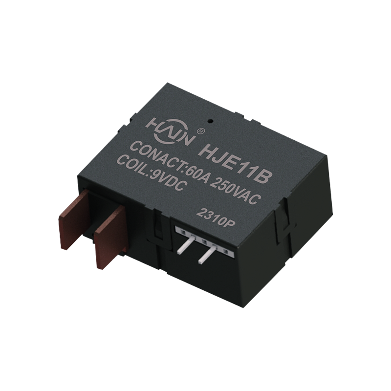 Wholesale HJE11B-60A Compliant with UC2 Single Phase Latching Relay Suppliers, OHuajin Technology Jiaxing Co., Ltd. is China wholesale HJE11B-60A Compliant with UC2 Single Phase Latching Relay suppliers and OEM/ODM co...View Product →
Dual-circuit meters, which serve two independent loads from one enclosure, use a two-channel relay or two separate single-pole relays. The mechanical behavior of both channels must be consistent, because both circuits are disconnected through the same command path.
DIN rail meters add a second constraint: the relay must fit the rail-mounted profile and often has to coexist with a shunt or current transformer inside the same enclosure. Manufacturers distinguish between split-type designs, where the relay and shunt CT are separate, and integrated designs, where a shunt or CT is built into the relay housing. The choice affects PCB layout, heat distribution, and whether the relay can be serviced without replacing the CT.
Three-phase meters demand a three-pole relay with enough contact gap to interrupt all phases simultaneously. For meters that target State Grid 25th Edition specifications, the relay must demonstrate compliance through the relevant type tests. The HJE33D120A 25th Edition State Grid three-phase latching relay is a 120 A example of this class, and for large commercial installations the same platform extends to higher current versions.
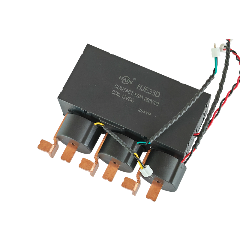 Wholesale HJE33D-120A 25th Edition State Grid Three Phase Latching Relay SupplieHuajin Technology Jiaxing Co., Ltd. is China wholesale HJE33D-120A 25th Edition State Grid Three Phase Latching Relay suppliers and OEM/O...View Product →
Multi-user meters, used in apartment blocks and commercial buildings, group several metering channels in one cabinet. These designs favor multi-circuit relay families that can be populated according to the number of users, with current ratings from 60 A to 80 A per channel.
AC charging stations use latching relays inside the power distribution unit to control the connection between the grid and the vehicle charger. These relays typically operate at 250 VAC with 120 A continuous current, and the main requirement is consistent contact behavior under repeated charging cycles. The HJE11F120A250VAC PDU latching relay addresses this duty with a 120 A contact rating on the same magnetic latching platform used in meter applications.
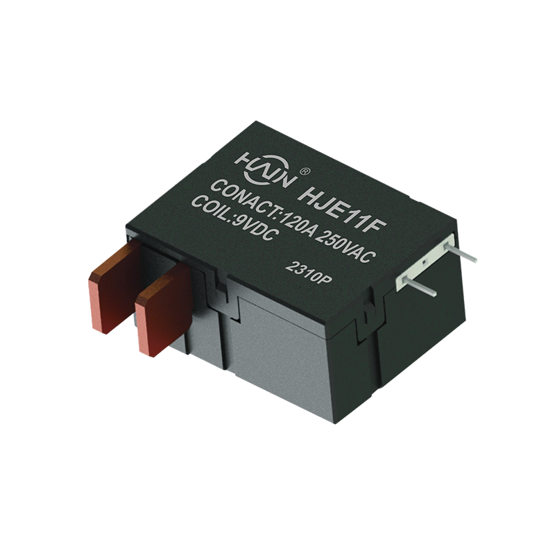 Wholesale HJE11F-120A-250VAC Latching Relay for PDU Suppliers, OEM/ODM CompanyHuajin Technology Jiaxing Co., Ltd. is China wholesale HJE11F-120A-250VAC Latching Relay for PDU suppliers and OEM/ODM company, Product O...View Product →
DC charging stations are a separate case. A DC charging post may switch 150 A at 48 VDC, where DC arc extinction requires a larger contact gap and specific contact materials. Choosing an AC-rated relay for a DC application is one of the most common specification errors in this area.
Overvoltage and undervoltage protectors use a relay that must hold its state during supply dips and then act decisively when the protected voltage crosses its threshold. The voltage-safety behavior of self-locking relays is directly relevant to these devices, because the self-locking coil holds the contact position without consuming power during normal operation.
Smart capacitor relays switch capacitor banks in reactive-power compensation equipment. Capacitor banks produce high inrush currents on closing, so the relay needs extra margin on contact welding resistance. Our note on how a relay operates inside a reactive-power compensation device explains the duty cycle and the failure modes to watch for.
Once the specification is fixed, supplier qualification becomes the main risk factor. A relay that passes type tests but varies in production can cause field failures months after installation. It is worth checking four things before approving a relay supplier.
Customization requests are normal in this product category. Meter manufacturers ask for specific coil voltages, terminal shapes, mounting heights, and whether a shunt or shunt CT should be integrated. A good supplier builds the custom version on a qualified platform rather than redesigning the relay from scratch, which keeps certification risk low while still matching the mechanical envelope of the meter.
The energy meter relay is a small line item in the bill of materials, but it decides whether a meter disconnects reliably, resists tampering, and survives a decade in the field. Specify the current and voltage classes correctly, verify standards compliance with documented test evidence, and qualify the supplier's production consistency before the design is locked.
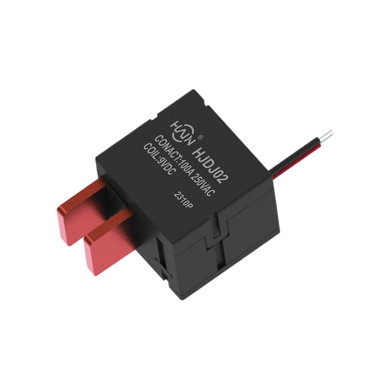
Product Definition: This product is a core control device designed for harsh industrial environments. Its key feature is its design specifically for high loads and complex electromagnetic environments...
See Details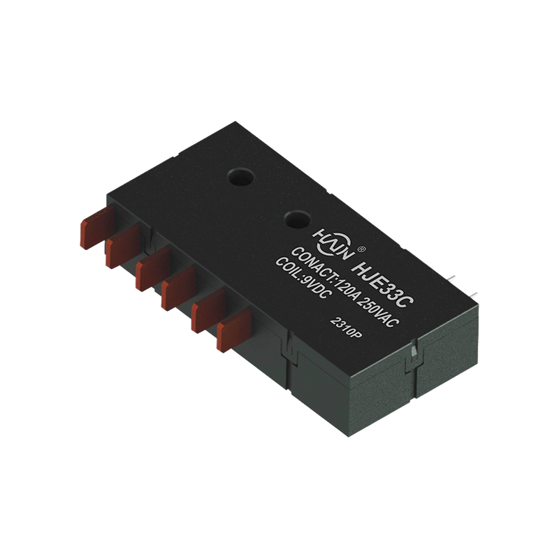
In industrial scenarios requiring reliable control of three-phase high-power loads, this product is a strategic choice for improving system energy efficiency and reliability. It not only meets the hig...
See Details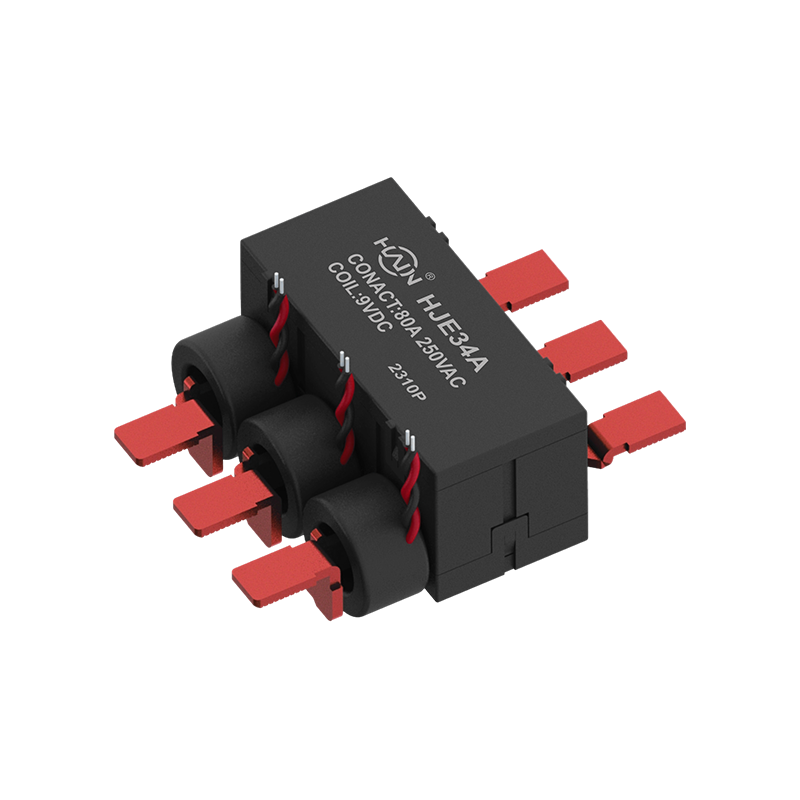
A Revolution in Integrated Three-Phase Power Control This is a highly integrated 4-pole three-phase rail relay, designed specifically for intelligent control and power distribution protection of three...
See Details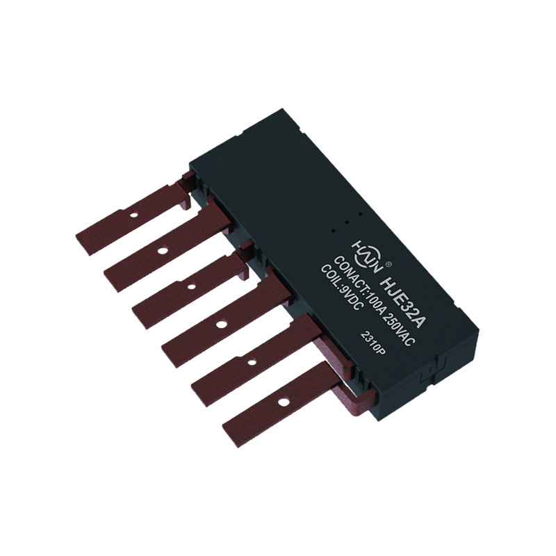
Product Definition: The HJE32A-100A is an innovative integrated three-phase relay designed specifically for 7P DIN rail meters. It aims to perfectly integrate three-phase metering and control, signifi...
See Details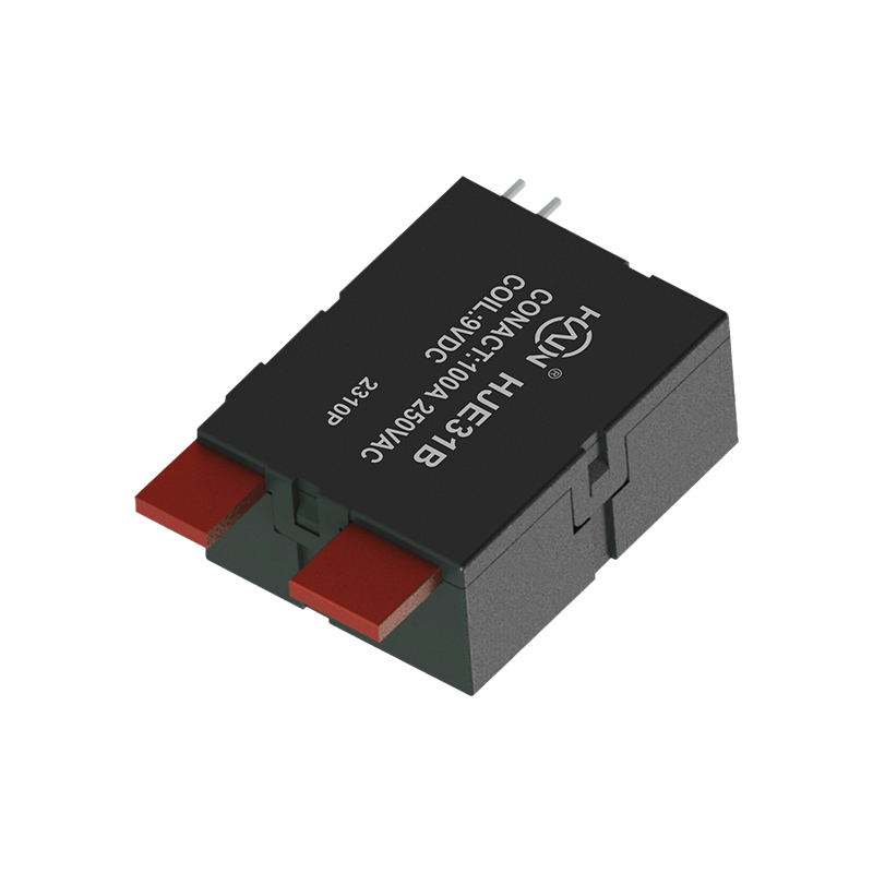
Product Definition: The HJE31B-100A is a split-type 7P DIN rail relay designed specifically for three-phase power systems. It features current monitoring, relay protection, and energy metering functio...
See Details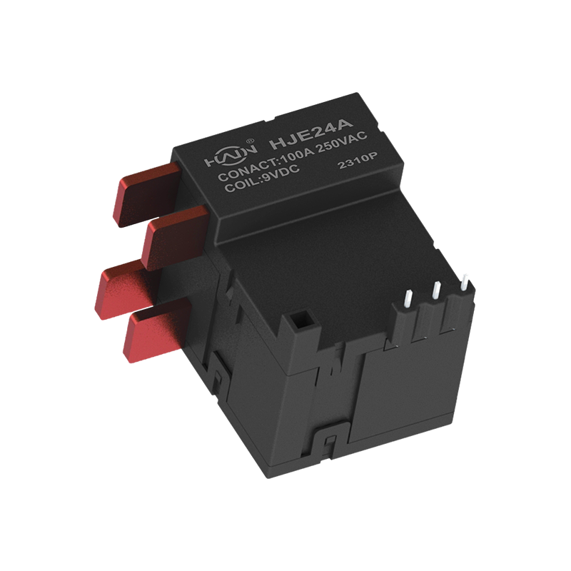
Dual-core drive, designed for demanding power control This is a high-current dual-channel relay compliant with UC3 safety standards, specifically designed for industrial scenarios requiring independen...
See Details
 Add.
Add.
|
No. 707, Yanyu Road, Yucheng Town, Haiyan County, Jiaxing City, Zhejiang Province, China
|
 Phone
Phone
|
+86-188-5739-7300
|
 Email.
|
alio@hj-relay.com
|
Copyright @ Huajin Technology Jiaxing Co., Ltd. All rights reserved.
