



 English
 中文简体
中文简体 русский
NEWS
 Home / News / Industry News / EV Charger Relay Selection: Latching Relays for AC and DC Charging Stations Home / News / Industry News / EV Charger Relay Selection: Latching Relays for AC and DC Charging Stations
Content
Charger programmes rarely fail because the connector was wrong. They fail because the switching element was chosen last, after the enclosure, the busbar layout and the thermal design had already been frozen. At that point a relay that is 6 mm too tall, or 20 A short of the required continuous rating, forces a redesign of the whole power module and pushes the certification schedule back by weeks.
An EV charger relay is the electrically controlled switch that connects the charging output to the vehicle and isolates it again the moment charging ends, the driver unplugs, or the control board detects a fault.
Four duties fall on that single component, and each one narrows the list of usable parts:
The charger class chooses the relay family, not the other way round. AC charging uses 250 VAC-class relays sized by per-phase current; DC charging uses 48 VDC or high-voltage DC devices sized by the full current of the output bus.
| Design factor | AC charging, 7-22 kW | DC charging, 50 kW and above |
| Switching voltage | 250 VAC, 50 or 60 Hz per pole | 48 VDC internal bus or high-voltage DC link |
| Continuous current | Up to 32 A per phase | 120 A to 150 A and above |
| Dominant stress | Thermal rise inside a sealed enclosure | DC arc duration and contact erosion |
| Typical device | Latching relay or AC contactor in the PDU | DC latching relay or DC contactor |
| Isolation focus | Supply to vehicle separation | Separation of DC bus sections |
AC designs generally settle on 60 A to 120 A contact ratings for a 32 A per-phase load, because the relay sits in a closed metal box where terminal temperature, not nominal current, is the limiting factor. A 120 A, 250 VAC latching relay in a power distribution unit leaves enough headroom for continuous operation at elevated ambient without forced air.
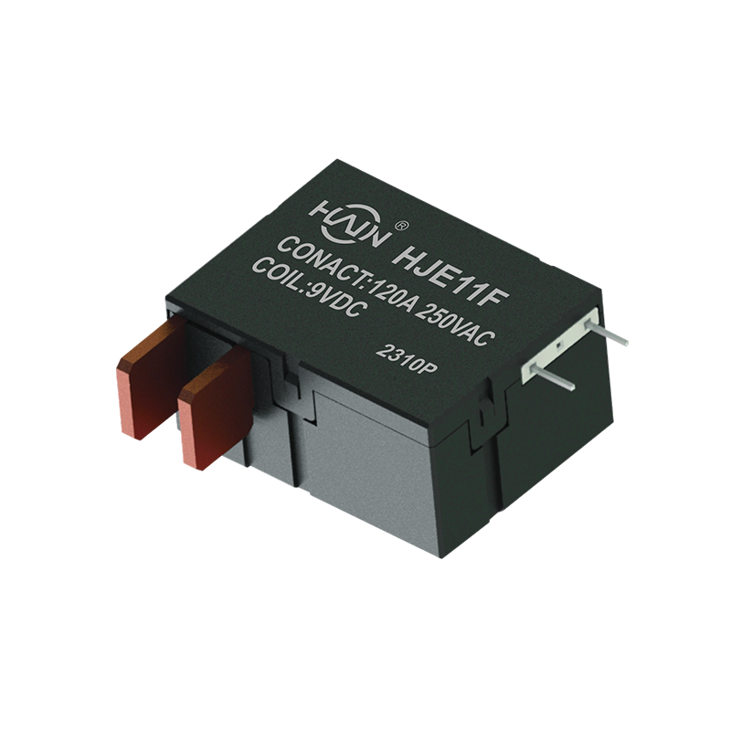 HJE11F 120A 250VAC Latching Relay for PCB PDUsPCB-mount 120 A/250 VAC latching relay for high-density PDUs, offering current headroom in closed enclosures and compact layout for data-center or industrial cabinets.View Product →
DC designs face the opposite problem. The current is high and the arc does not self-extinguish at a zero crossing, so the relay needs a wider contact gap, stronger contact pressure and often magnetic arc blowout. Selection criteria for both families are set out in more detail in this charging station relay guide.
Five specifications separate a relay that completes 10,000 cycles from one that welds at 3,000: contact rating with derating, inrush capability, electrical life, coil drive, and thermal behaviour at the terminal.
Where a charger needs both current margin and a low profile, a 120 A, 250 VAC latching relay with an integrated body is the usual starting point for the shortlist.
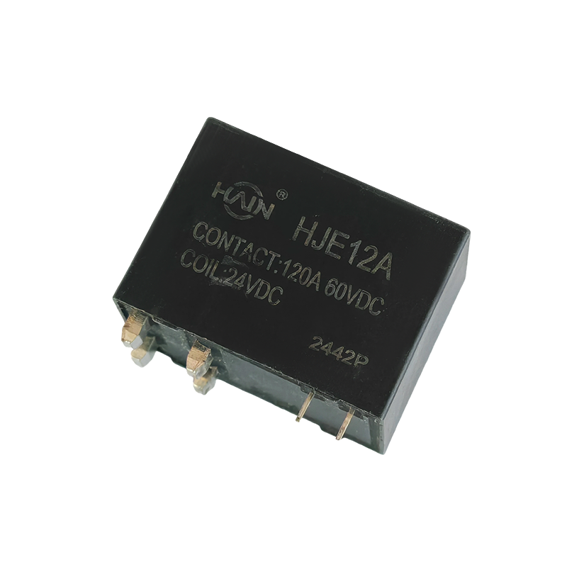 HJE12A 120A 250VAC Through-Hole Latching Relay for Rack PDUsThrough-hole 120 A/250 VAC latching relay for rack-mount PDUs, combining current margin with low-profile density and pulse-only coil consumption for charger designs.View Product →
A magnetic latching relay consumes power only during the switching pulse, which removes the standing coil loss, the standing heat and the dependence on continuous control power that a conventional relay imposes on a charger.
Inside the device, a permanent magnet holds the armature in its last position, and a short coil pulse of opposite polarity flips it. Typical pulse widths run from 10 to 20 milliseconds, and holding current is zero. The consequences for a charger design are concrete:
A conventional relay holding 1 W per pole around the clock adds roughly 8.8 kWh of loss per year and keeps a constant heat source next to the terminals, which matters when the enclosure already runs close to its thermal limit. Latching versions also retain the output state through a control-board reset, so a charger does not drop a session every time the logic supply flickers.
DC output stages use the same principle at higher current, where a 48 VDC, 150 A latching relay takes over the switching function inside the power module.
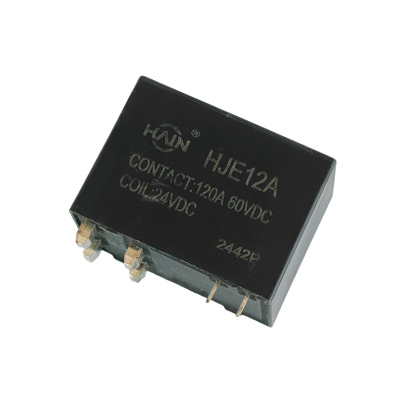 HJE12A 150A 48VDC Latching Relay for DC Charging150 A/48 VDC latching relay with double contacts and magnetic blowout for DC charging power modules, where arc erosion and contact welding are key concerns.View Product →
Contact welding, DC arc erosion and terminal overheating account for most relay-related returns, and all three can be predicted and removed at the design stage.
Qualification is a document-and-data exercise: certificates, endurance reports, derating curves and production capacity belong on the table before samples are approved, because a relay that passes on a bench sample can still drift in mass production.
As an example of the scale worth looking for, Huajin Technology Jiaxing Co., Ltd. operates an 8,000 square metre plant in Haiyan County, Zhejiang, with more than 120 employees and a stated capacity above 10 million magnetically latching relays per year, around 30 percent of which is exported. Its ranges cover AC and DC charging PDUs, DIN rail meters, overvoltage and undervoltage protectors and smart capacitors, so a charger project can qualify its switching element and its meter relays against one set of documents.
AC chargers use 250 VAC latching relays or contactors in the power distribution unit, sized at 60 A to 120 A for a 32 A per-phase output. DC chargers use 48 VDC or high-voltage DC relays, typically 120 A to 150 A, which must break a DC arc without a natural current zero crossing.
Start from 32 A per phase at 400 VAC, then apply margin for enclosure temperature and inrush. In practice this lands on 60 A to 120 A rated contacts per pole, a rating confirmed by temperature rise testing rather than by nominal current alone.
A latching relay holds its state through a permanent magnet after a 10 to 20 millisecond coil pulse, so holding power is zero. That removes continuous coil heat from a sealed enclosure and keeps the output state stable through a control power interruption.
Ask for electrical life figures at rated load and at the working ambient temperature. A relay intended for charger duty should be documented for thousands of on-load operations, and the derating curve should show what happens above 60 C ambient.

Product Definition: The HJE12A-150A-48VDC is a high-performance DC relay designed specifically for 48VDC voltage systems, with a maximum current carrying capacity of 150A. It features excellent switch...
See Details
The Powerful Core of the PDU! The HJE12A-120A is a PCB-based through-hole high-power relay designed specifically for rack-mount power distribution units (PDUs), aiming to achieve PDU miniaturization, ...
See Details
Product Overview: Designed specifically for high-density power distribution units (PDUs), this high-power control core is directly integrated into the PCB board. With a robust 120A/250VAC load capacit...
See Details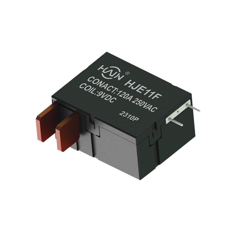
Product Definition: The HJE11F-120A-250VAC is a high-performance magnetic latching relay designed specifically for undervoltage protection systems. It supports a maximum current of 120A and is suitabl...
See Details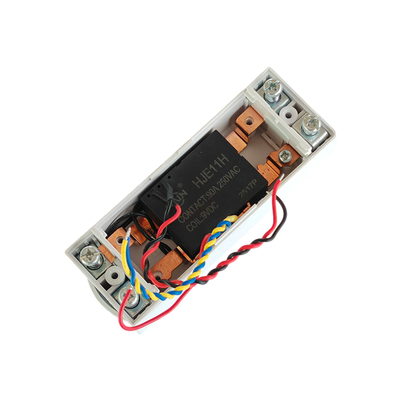
Product Definition:This product is a top-in, bottom-out 2-pole DIN rail relay designed specifically for modern power distribution systems. It integrates a 90A high current carrying capacity, compact s...
See Details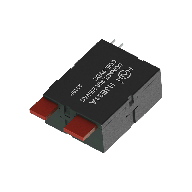
Product Definition: A bottom-in, bottom-out relay specifically designed for 2P DIN rail meters, aiming to improve installation efficiency and system reliability through optimized wiring structure.
See Details
 Add.
Add.
|
No. 707, Yanyu Road, Yucheng Town, Haiyan County, Jiaxing City, Zhejiang Province, China
|
 Phone
Phone
|
+86-188-5739-7300
|
 Email.
|
alio@hj-relay.com
|
Copyright @ Huajin Technology Jiaxing Co., Ltd. All rights reserved.
