



 English
 中文简体
 русский
NEWS
 Home / News / Industry News / Latching Relay Selection Guide: Contact Ratings, Pulse Drive and Meter Fit Home / News / Industry News / Latching Relay Selection Guide: Contact Ratings, Pulse Drive and Meter Fit
Content
A 100 A single-phase wall-mounted meter has to hold its last switching state through a 12-hour blackout, carry a household's full service current without welding its contacts shut, and survive thousands of make-and-break cycles. The component that does all three is a latching relay, and it does them while drawing no power at all once it has switched.
A latching relay is a two-position electromechanical switch that changes state on a short electrical pulse and then holds that state mechanically, with no coil current, until a second pulse reverses it.
That definition carries more engineering weight than it first appears. A conventional power relay depends on a return spring to pull its contacts back to the rest position, so its coil has to stay energized for as long as the load must stay connected. A magnetic latching relay replaces the return spring with a permanent magnet, which supplies the holding force in both positions. The coil only has to overcome that magnet for the few milliseconds needed to move the armature.
Terminology note: latching relay, bistable relay, magnetic latching relay and impulse relay all describe the same device family. In metering, the word that matters is "magnetic" - the holding force comes from a permanent magnet rather than a mechanical detent, which is why the contact state survives shock, vibration and a complete loss of control power.
Two-coil designs use separate set and reset windings. A low-side MOSFET on each winding is enough, polarity never has to reverse, and the firmware stays simple. Single-coil designs save pins but force the driver to reverse current through the same winding, which means an H-bridge or a bipolar supply. In a meter where the relay sits next to a shunt and a metering ASIC, the two-coil layout is usually the easier one to keep clean.
Drive the coil with a defined 10 to 20 ms pulse and then remove it. A longer pulse does not press the contacts any harder; it only heats a winding that was never rated for continuous duty.
A metering-grade latching relay coil is built for intermittent operation. At 12 V DC with a coil resistance in the tens of ohms, it pulls a few hundred milliamps for the duration of the pulse. At 300 mA and 12 V that is 3.6 W of instantaneous dissipation, but only for about 20 ms, which works out to roughly 0.07 J of energy per operation. Even across 10,000 electrical operations in a fifteen-year meter life, the coil never consumes more than a fraction of a kilojoule in total.
That comparison is the reason latching relays dominate electricity metering. A smart meter's entire internal supply budget is only a couple of watts, shared between the metering front end, the display and the communication module. A coil demanding 1.5 W to 2 W continuously would consume more than everything else in the meter combined.
Practical drive notes: give each coil its own flyback diode or RC snubber, generate the pulse from a hardware timer rather than a software delay, and make sure a retriggered interrupt cannot stretch it. Inside a sealed meter enclosure there is nowhere for stray coil heat to go, and a winding left energized by a firmware bug will eventually cook its own insulation.
Size the latching relay by the meter's maximum current, Imax, and by its utilization category. The nominal base current, Ib, tells you almost nothing about which contact system the application actually needs.
IEC 62055-31, the standard covering latching relays for electricity metering, sorts these devices into utilization categories UC1 through UC5. A higher category means higher making and breaking capability, a more severe test sequence, and usually a heavier contact system inside. In practice, 60 A and 80 A single-phase parts sit in UC2, while 100 A to 120 A parts qualified to UC3 carry more silver alloy and stiffer contact springs to survive the switching tests.
China's State Grid 25th Edition specification for smart electricity meters moved three-phase meter designs toward 120 A contact systems. A part carrying a 25th Edition designation is built and tested against that document rather than against a generic catalogue rating, which matters when a utility tender references it by name.
The step from 100 A to 150 A is not a rounding difference. Contact force, silver alloy mass, terminal cross-section and the internal busbar all scale up together. That is why a 150 A part is normally reserved for three-phase switching or for the 48 VDC load path of a DC charging pile, while household single-phase metering stays in the 60 A to 120 A band.
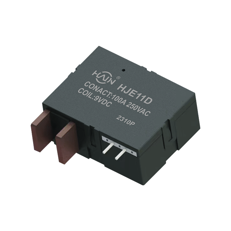 HJE11D-100A UC2 Single-Phase Latching Relay100 A single-phase latching relay with UC2 compliance, pulse-driven coil, and compact PCB mount for smart metering and energy-saving switching.View Product →
Two numbers pick the family: Imax sets the contact rating, and the utilization category sets the test regime the part has to survive.
The same 100 A magnetic latching relay platform can serve a wall-mounted meter, a DIN rail meter and a three-phase capacitor switch, but the form factor, the current path and the reset method change with the application.
| Application | Contact rating | Switching voltage | Typical form factor |
| Single-phase wall-mounted meter | 60-120 A | 250 VAC | PCB or busbar mount, UC2 to UC3 |
| Three-phase / 7P DIN rail meter | 100-120 A per pole | 250 VAC | Split type, integrated, with shunt or CT |
| Multi-user meter cabinet | 60-90 A | 250 VAC | Multi-circuit split type |
| AC charging pile PDU | 120 A | 250 VAC | Panel mount inside the PDU |
| DC charging pile | 150 A | 48 VDC | High-current DC switching path |
| Overvoltage / undervoltage protector | 60-150 A | 250 VAC | DIN rail module |
| Three-phase smart capacitor | 60-120 A | 250 VAC | Capacitor housing, reactive power switching |
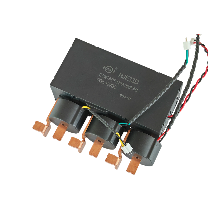 HJE33D-120A State Grid Three-Phase Latching RelayThree-phase magnetic latching relay built to State Grid standards for protection circuits, maintaining state through outages and fitting distribution and industrial control panels.View Product →
Read that table by column, not by row. Contact rating and switching voltage decide which relay family fits. The form factor decides whether the part can physically sit next to a shunt, a current transformer or a 7P DIN rail terminal block without a redesign of the meter chassis.
Component supply is the other half of the specification. Huajin Technology Jiaxing Co., Ltd., based in Yucheng, Haiyan County, Jiaxing, Zhejiang, was founded in May 2021 and runs an 8,000 square metre plant with more than 120 employees and an annual capacity above 10 million magnetic latching relays, roughly 30 percent of which is exported. The company cites ISO 9001-2015, CCC and TUV certification, along with State Grid qualification for its metering relays. For a buyer, the question that decides the award is narrower than certification: it is whether the supplier can hold contact resistance, timing and pulse sensitivity consistent across a million units, not just across the first sample batch.
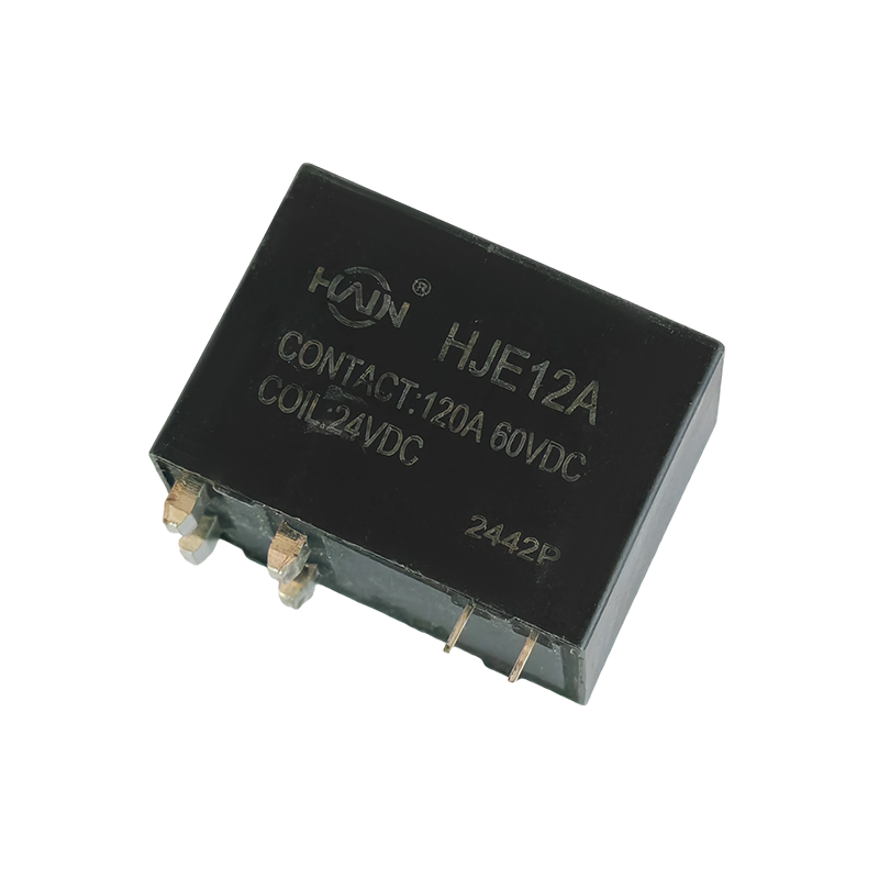 HJE12A-150A 48 VDC Latching Relay for DC Charging150 A, 48 VDC latching relay with double contacts and auxiliary status switch for EV charging, solar, and industrial DC switching.View Product →
If the specification is still open, this comparison of latching relay types and selection for DIN rail meters walks through the split, integrated, shunt and CT variants side by side.
Run these five checks on the sample before the part number goes into the bill of materials. Each one catches a failure mode that never appears in a catalogue rating.
The failure that hurts most is not a dead relay. It is a part that passes 100 operations on the bench and starts drifting at 3,000, long after the meter has been sealed and shipped.
No. Once the set pulse has moved the armature, a permanent magnet holds the contacts in that position with zero coil current. Power is only required for the 10 to 20 ms it takes to change state, which is why the device is also called a bistable or magnetic latching relay.
It stays exactly where it was. A power failure removes the coil pulse but not the magnetic holding force, so a meter fitted with a latching relay keeps supplying the load through an outage and resumes normal operation when the supply returns. A conventional relay would release its contacts the moment the coil lost current.
Not directly. A metering-grade coil draws a few hundred milliamps at 12 V, far beyond the safe output of a general-purpose GPIO pin. Use a MOSFET or a dedicated driver per coil, drive the pulse from a hardware timer, and add a flyback path so the collapsing field does not damage the driver.
Metering-grade parts are specified for around 10,000 electrical operations at rated current and for a much higher number of mechanical operations. Electrical life is dominated by arc energy at the instant the contacts open, so a 100 A part switching a 250 VAC load ages far faster than the same part switching a low-current control circuit.
Pick the utilization category first, then the contact rating, then the form factor. Everything else about a latching relay, from pulse width to terminal plating, follows from those three decisions.
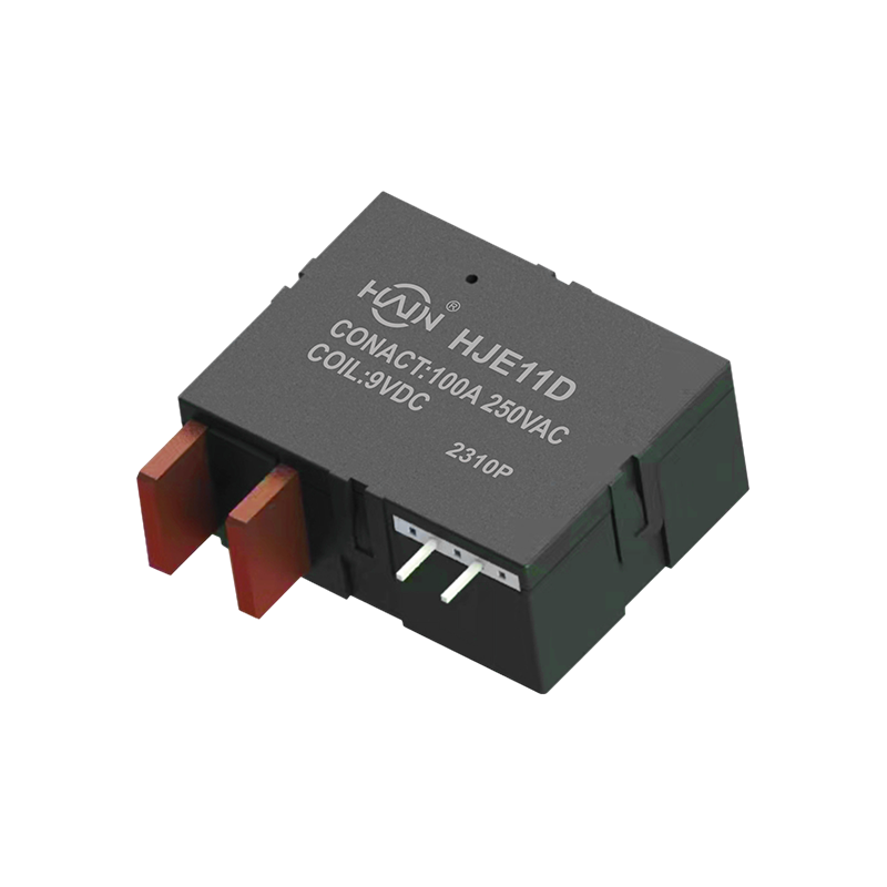
Redefining the DIN rail meter, one chip solves two major problems! The HJE11D-100A is a high-current relay with metering function designed specifically for 4P DIN rail energy meters. It aims to solve ...
See Details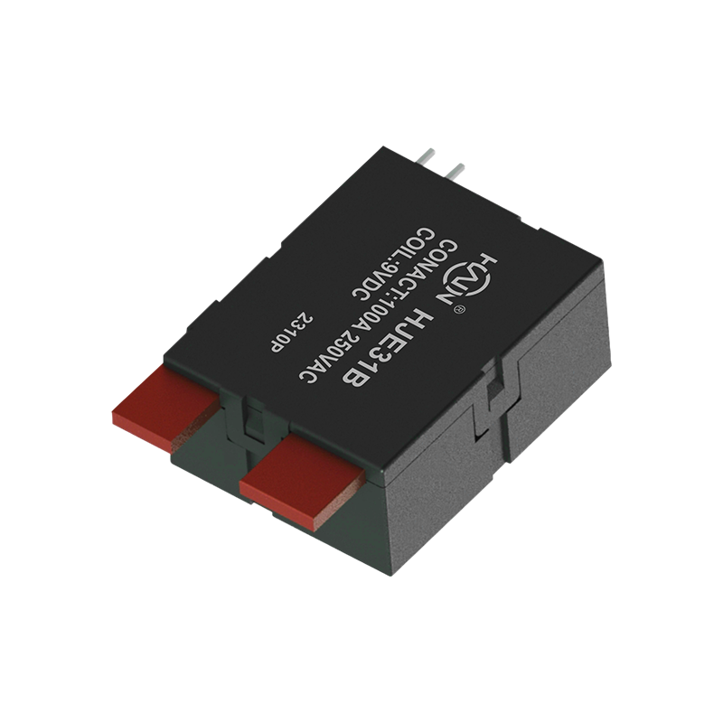
Product Definition: The HJE31B-100A is a split-type 7P DIN rail relay designed specifically for three-phase power systems. It features current monitoring, relay protection, and energy metering functio...
See Details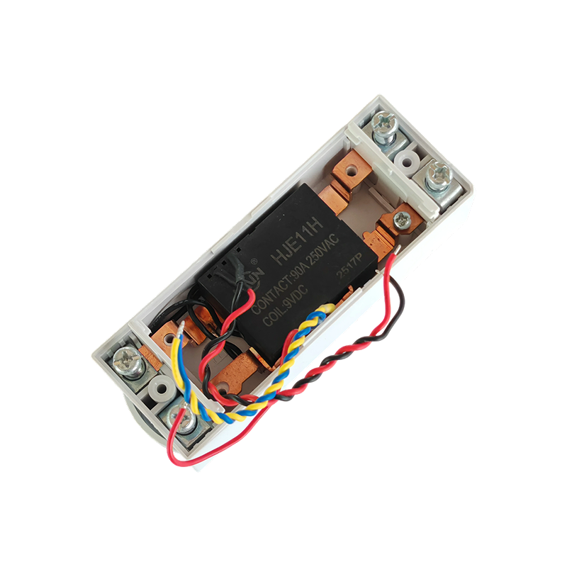
Product Definition:This product is a top-in, bottom-out 2-pole DIN rail relay designed specifically for modern power distribution systems. It integrates a 90A high current carrying capacity, compact s...
See Details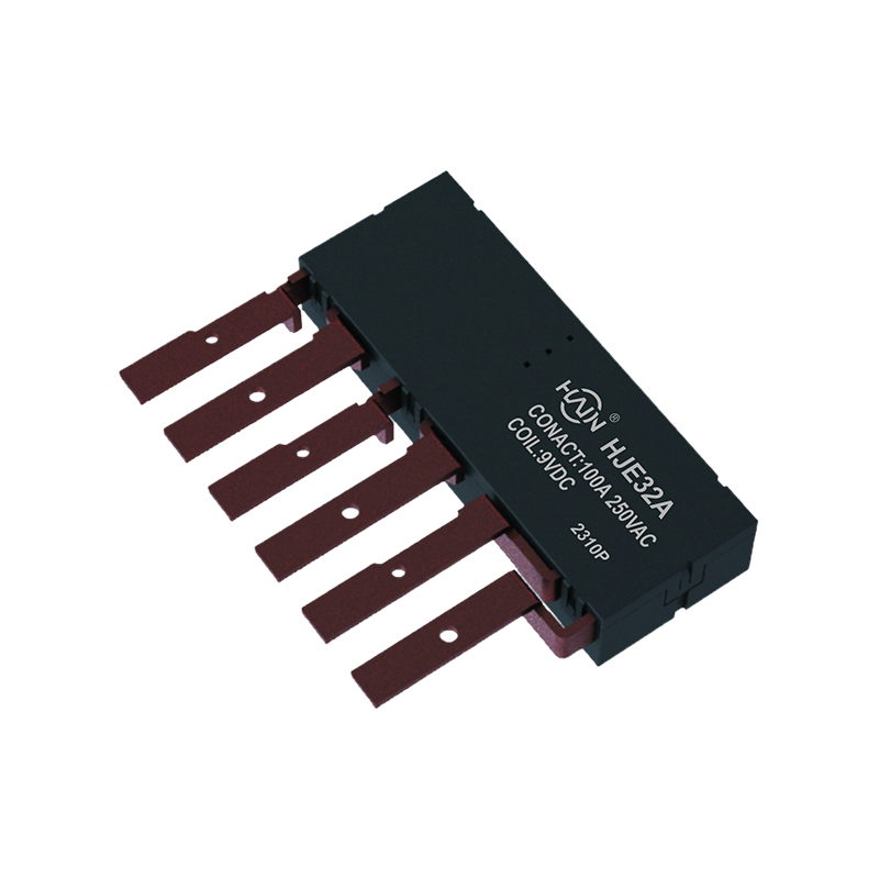
Product Definition: The HJE32A-100A is an innovative integrated three-phase relay designed specifically for 7P DIN rail meters. It aims to perfectly integrate three-phase metering and control, signifi...
See Details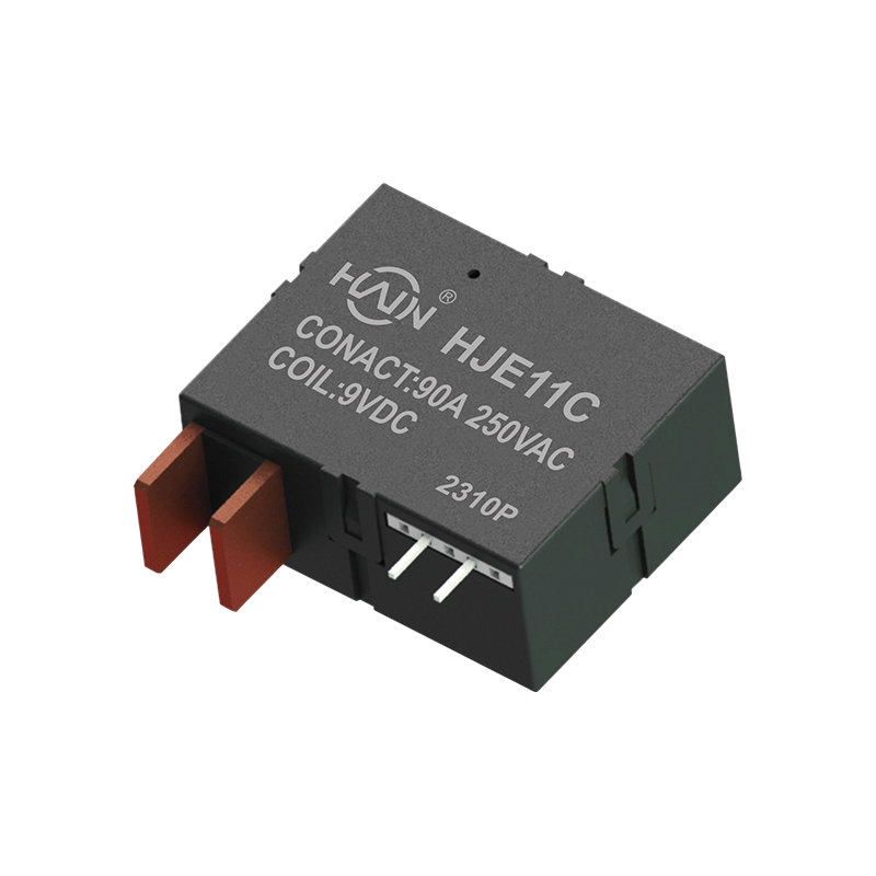
Product Definition: This product is a four-pole DIN rail relay integrating power metering and relay protection functions. Designed specifically for power metering systems, it is widely used in residen...
See Details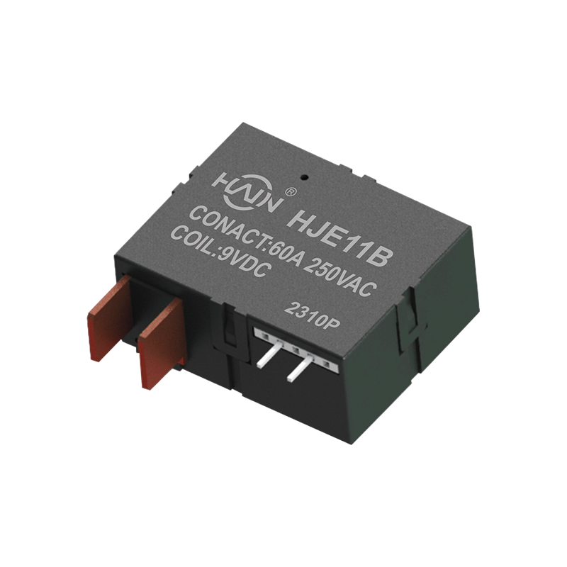
A Power Management Expert Integrating Control and Metering In increasingly complex industrial and commercial power distribution environments, refined power management and reliable control are equally ...
See Details
 Add. |
No. 707, Yanyu Road, Yucheng Town, Haiyan County, Jiaxing City, Zhejiang Province, China
|
 Phone |
+86-188-5739-7300
|
 Email. |
alio@hj-relay.com
|
Copyright @ Huajin Technology Jiaxing Co., Ltd. All rights reserved.
