



 English
 中文简体
中文简体 русский
NEWS
 Home / News / Industry News / Relay for DC Charging Station: 48VDC 150A Latching Relay Guide for EV Chargers Home / News / Industry News / Relay for DC Charging Station: 48VDC 150A Latching Relay Guide for EV Chargers
When an EV is plugged into a DC fast charger, the first switching decision is made by a latching relay inside the power distribution unit (PDU). The relay closes to connect the charging current, and it must open just as decisively when the session ends or when a fault is detected. In DC fast charging, the relay is not an accessory: it is a safety and performance component that must carry high current continuously and interrupt DC load current reliably.
DC fast charging follows the Mode 4 principle defined in IEC 61851. The station converts a three-phase AC supply into controlled DC and feeds the vehicle battery directly, bypassing the onboard charger. Because a DC waveform has no natural zero crossing, the arc created when the relay opens at load current does not extinguish by itself. The contact gap, the arc chamber and the contact materials have to break that arc on every operation. Selecting a relay for DC charging station applications therefore starts with DC interruption behaviour, not with the continuous rating alone.
The safety implications extend across the whole charging system. The safety benefits of a charging station depend on every switching element performing under load; a relay that welds its contacts during a fault can leave the battery connected, which is the worst single failure mode for a charging pile.
Engineers selecting a relay for a new DC charging pile usually settle on four parameters. The table below summarises what to compare and why.
| Parameter | Why it matters | Typical direction for DC charging |
|---|---|---|
| Continuous contact current | Determines temperature rise and derating inside the PDU enclosure | 150 A or higher, verified at the maximum ambient temperature of the pile |
| DC breaking capability | DC arcs cannot rely on an AC zero crossing; the relay must quench the arc by itself | Larger contact gap with a proven arc-quenching structure |
| Coil drive interface | Latching relays hold their state without holding current, saving standby power | 48 VDC pulse, single or double coil, short pulse energy |
| Endurance | Determines maintenance intervals and lifecycle cost of the pile | Electrical endurance at rated current, not only mechanical endurance |
At 150 A on a DC bus, opening the contacts at full current is a harsher event than switching the same current on AC. Line-frequency AC gives the relay many natural zero crossings per second to cool and clear the arc. A DC relay must stretch the arc, cool it and establish a contact gap before the voltage can restrike. For that reason, a DC-rated relay is rarely a drop-in replacement for an AC relay of the same nominal current, even if the continuous rating looks identical.
A magnetic latching relay changes state with a short coil pulse and remains in that state with zero coil power. A charging pile can spend many hours per day in standby, so eliminating continuous coil dissipation reduces the temperature inside the PDU. A cooler enclosure improves the derating margin of the surrounding electronics, which is an indirect but measurable benefit in DC power designs.
Most charging-pile control boards in our engineering practice operate with a 48 VDC auxiliary rail, and the relay coil is driven from that rail through a capacitor-discharge circuit. Two parameters matter. The first is pulse width: it must be long enough to guarantee a state change at low ambient temperature. The second is the suppression circuit: a poorly designed freewheeling path can cause the latching relay to bounce back into its previous state. Verifying both on the actual control board is part of any serious relay qualification.
Because AC and DC piles are sold into the same infrastructure market, buyers often ask whether one relay can cover both applications. The underlying relay platform is similar, but the ratings and the verification focus are not.
Our AC charging range includes a 120 A 250 VAC latching relay for PDU applications, sized for the AC load profile and the PDU board layout. On the DC side, the 150 A 48 VDC latching relay for DC charging pairs a 48 V DC coil interface with a 150 A contact system designed for DC switching duty. Choosing the relay that matches the station type avoids both the cost of over-specification and the risk of under-rated field failure.
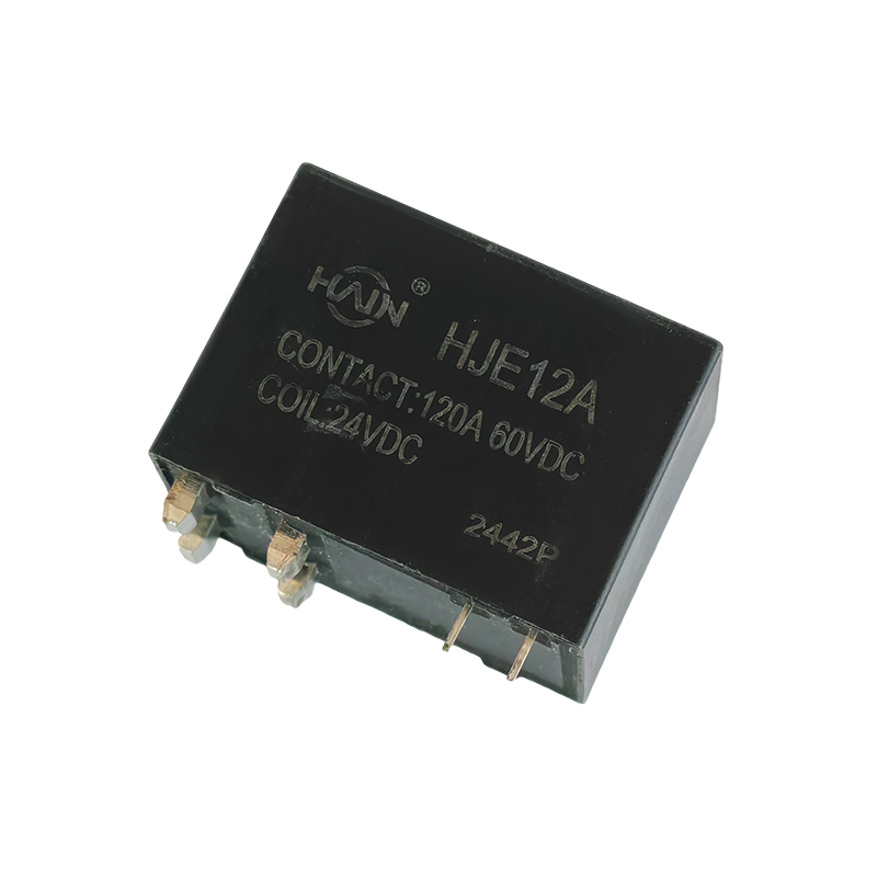 Wholesale HJE12A-150A-48VDC Latching Relay for DC charging Suppliers, OEM/ODM CoHuajin Technology Jiaxing Co., Ltd. is China wholesale HJE12A-150A-48VDC Latching Relay for DC charging suppliers and OEM/ODM company, Pr...View Product →
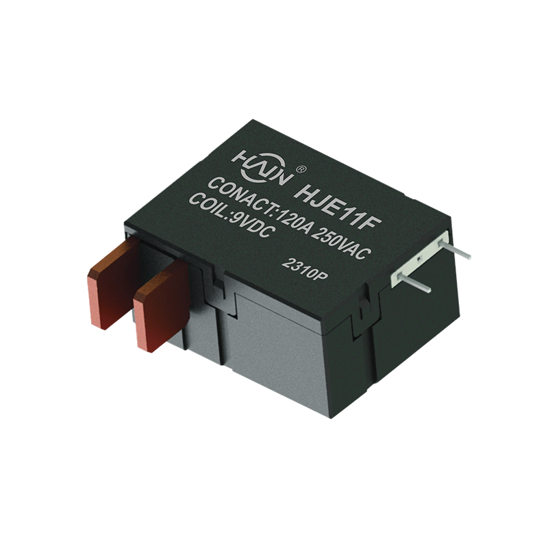 Wholesale HJE11F-120A-250VAC Latching Relay for PDU Suppliers, OEM/ODM CompanyHuajin Technology Jiaxing Co., Ltd. is China wholesale HJE11F-120A-250VAC Latching Relay for PDU suppliers and OEM/ODM company, Product O...View Product →
Charging piles switch far less often than electricity meters, but each operation is electrically severe. The dominant wear mechanism is contact erosion caused by DC arcs at high current. When comparing relays, look for electrical endurance values measured at rated load and at a realistic ambient temperature. Mechanical endurance figures alone can be misleading, because a latching mechanism can outlive its contacts by a wide margin.
The same engineering discipline shows up in the metering industry, where high-reliability control for smart meters depends on contact material and coil stability across millions of pulses. The philosophy transfers directly to charging piles: verify the contact material, the insulation system and the production tolerances on real samples, not only on the datasheet.
Charging-station OEMs, in our experience, ask three questions before sampling: Is the relay TUV-certified? Does it carry CCC marking? Is the factory ISO9001-certified? For programs tied to utility or grid infrastructure, evidence related to State Grid requirements is also part of the supplier audit. These checks exist because the relay becomes part of a product used in public infrastructure, exposed to weather, vibration and non-expert users.
At the bench stage, we recommend running three tests on the first batch: dielectric strength between coil and contacts, insulation resistance, and temperature rise at rated current. Performing these tests on production samples rather than engineering samples gives a realistic view of the relay that will actually be shipped.
The selection of a relay for DC charging station hardware can be condensed into five practical points.
Huajin Technology's background illustrates the supply-side question that OEMs should ask. The history of Huajin Technology Jiaxing shows a relay manufacturer that grew from metering relays into charging-station products, with an annual production capacity of more than ten million latching relays and export sales of about 30 percent. A facility of that scale can support standard product supply as well as custom coil and terminal variants for a specific charging-pile programme.
Get the contact system and the coil interface right, and the rest of the PDU design has a simpler job. That is why the relay should be locked down early in a DC charging station project.

Product Definition: The HJE12A-150A-48VDC is a high-performance DC relay designed specifically for 48VDC voltage systems, with a maximum current carrying capacity of 150A. It features excellent switch...
See Details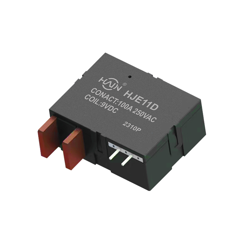
Redefining the DIN rail meter, one chip solves two major problems! The HJE11D-100A is a high-current relay with metering function designed specifically for 4P DIN rail energy meters. It aims to solve ...
See Details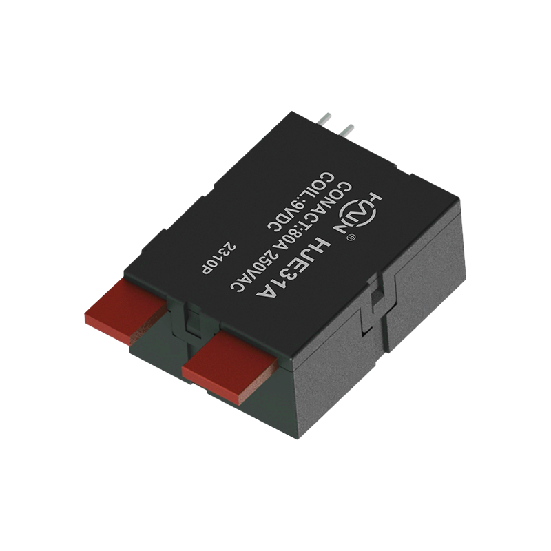
Product Definition: A bottom-in, bottom-out relay specifically designed for 2P DIN rail meters, aiming to improve installation efficiency and system reliability through optimized wiring structure.
See Details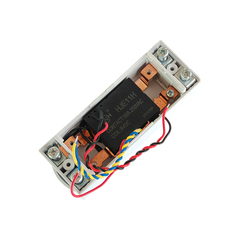
Product Definition:This product is a top-in, bottom-out 2-pole DIN rail relay designed specifically for modern power distribution systems. It integrates a 90A high current carrying capacity, compact s...
See Details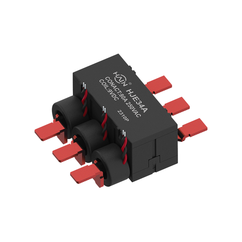
A Revolution in Integrated Three-Phase Power Control This is a highly integrated 4-pole three-phase rail relay, designed specifically for intelligent control and power distribution protection of three...
See Details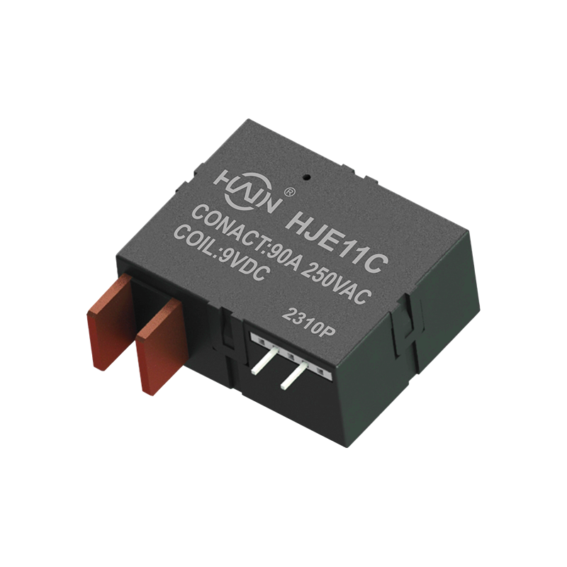
Product Definition: This product is a four-pole DIN rail relay integrating power metering and relay protection functions. Designed specifically for power metering systems, it is widely used in residen...
See Details
 Add.
Add.
|
No. 707, Yanyu Road, Yucheng Town, Haiyan County, Jiaxing City, Zhejiang Province, China
|
 Phone
Phone
|
+86-188-5739-7300
|
 Email.
|
alio@hj-relay.com
|
Copyright @ Huajin Technology Jiaxing Co., Ltd. All rights reserved.
