



 English
 中文简体
中文简体 русский
NEWS
 Home / News / Industry News / Relay for AC Charging Stations: How to Select the Right Latching Relay Type Home / News / Industry News / Relay for AC Charging Stations: How to Select the Right Latching Relay Type
Content
A 22 kW single-phase AC charging station operating at 250 VAC can draw up to 88 A of continuous current while a vehicle charges. When the session ends, the relay inside the power distribution unit has to open that circuit without welding its contacts. If that relay fails, the station goes offline at peak hours and the operator loses revenue. The relay for AC charging stations is the component that determines whether a charging session becomes a completed transaction. Huajin Technology Jiaxing Co., Ltd., a latching relay manufacturer with an annual output capacity exceeding 10 million units, produces two relays rated for AC charging PDU duty: the HJE11F120A and the HJE12A120A.
Core definition: A latching relay for AC charging stations is a bistable electromechanical switch that changes contact state with a short coil pulse and holds that state without any continuous coil current. This zero-hold-power characteristic makes it the standard choice for switching 60-120 A mains circuits in sealed PDUs.
The relay in an AC charging station decides whether a session completes by switching AC mains power to the vehicle's onboard charger and by interrupting that current at the end of the charge. It is also the first component an EVSE commissioning engineer tests when a station will not start, because an open contact on the line side stops all charge current before it reaches the vehicle.
At 11 kW three-phase, each phase sees around 28 A at 230 VAC. At 22 kW single-phase, the current reaches roughly 88 A at 250 VAC. The HJE11F120A latching relay for PDU is rated at 120 A / 250 VAC and is marked UC3-compliant, giving designers the headroom they need for a 22 kW charger.
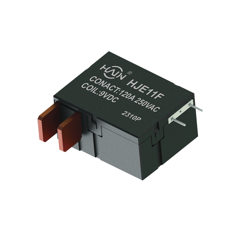 HJE11F-120A Latching Relay for PDU with 250VAC RatingThis 120A latching relay handles 250VAC and is UC3-compliant, offering ample headroom for high-power 22kW charging PDU designs. Its PCB integration saves space while ensuring reliable switching.View Product →
Common failure modes in undersized relays include:
Each one maps to a specification: arc erosion relates to contact material and gap; welding relates to inrush and contact force; coil heat relates to latching versus continuous duty.
Four specifications determine whether a relay fits an AC charging station: rated current, coil drive voltage and pulse width, contact configuration, and clearance and creepage distance. A designer who compares only current rating and voltage will end up with a relay that fails on the control side or on insulation distance.
Continuous current is the easy number. Inrush is the harder one. When the onboard charger powers up, its input capacitors draw a brief spike that can exceed the steady-state value several times. The relay must carry that spike without contact transfer. Moving from an 80 A rated appliance relay to a 120 A PDU relay is a meaningful jump in physical size, not just a label change.
| Model | Rated Current | Contact Voltage | Compliance | Application |
| HJE11F120A | 120 A | 250 VAC | UC3 | AC charging PDU |
| HJE12A120A | 120 A | 250 VAC | UC3 | AC charging PDU |
Latching relays change state with a single DC pulse, typically 9-48 VDC and 50-200 ms. Once the contacts close, the coil current falls to zero. The control board only needs to drive the relay channel during the transition, which removes a continuous current path from the sealed enclosure. The pulse width must be long enough to complete the mechanical travel but short enough to avoid heating the coil.
Contact configuration determines how many conductors the relay can switch. AC charging PDU designs often switch line and neutral together, so a single circuit with a 1A/1B contact set is common for 22 kW single-phase chargers. The HJE12A120A was designed for PDU duty in AC charging stations and provides a 250 VAC 120 A contact set in a compact package.
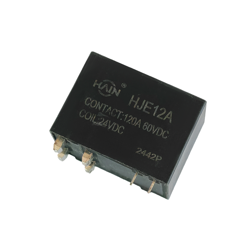 HJE12A-120A Latching Relay for AC Charging Station PDUsDesigned for AC charging station PDUs, this compact 250VAC/120A latching relay features through-hole PCB mounting, simplifying assembly and enabling high-density power distribution in racks.View Product →
For a detailed walkthrough of contact arcing and relay operation in charging infrastructure, the charging station relay guide is a useful resource.
A latching relay for AC charging stations dissipates effectively zero power after switching, because the contacts are held by residual magnetic force rather than by continuous coil current.
Sealed charging station PDUs have a strict thermal budget. Every watt of coil power in a standard relay becomes heat inside that sealed volume. In a cabinet housing three 22 kW chargers, 1.5 W of idle coil dissipation per relay adds up to a measurable temperature rise. The common ambient range for EVSE equipment is -25 to +55 C, so any additional heat source reduces the allowed temperature rise margin for power electronics on the same PDU.
Illustrative comparison of idle coil dissipation.
The switch contact itself generates I2R heat during current flow, but the coil circuit contributes nothing once the state is stable. This is why most high-current AC charging station relays are latching rather than continuous-duty.
An AC charging station relay must satisfy both the electrical protection standards and the infrastructure standards of the destination market. In China, UC2/UC3 and the 25th edition State Grid standard are referenced; for export projects, TUV and CCC certification and IEC 61851-1 requirements all apply.
Huajin Technology Jiaxing Co., Ltd. lists UC3 compliance on the 120 A AC charging PDU relays, and the broader product line has passed TUV, CCC, and State Grid certification. Checking the relay against the insulation coordination of the charger itself is as important as comparing contact ratings. In an AC charging station, the relay is located between the grid connection and the vehicle connector, so its clearance and creepage determine whether a surge from the grid can jump across the relay contact gap.
Key certification points to verify:
For a station-level view, the safety benefits of using a charging station explain how component reliability translates into site protection.
Latching relays outperform standard electromechanical relays in AC charging PDUs because they eliminate coil hold current, reduce temperature rise, and are available in 120 A or higher ratings for 250 VAC circuits.
| Feature | Latching Relay | Standard Electro relay |
| Idle coil power | about 0 W | 0.5-2 W |
| Contact rating at 250 VAC | 120 A and above | 80 A common ceiling |
| Temperature contribution in PDU | Minimal | Significant in sealed enclosures |
| Control logic | 50-200 ms pulse | Continuous hold |
One practical difference that affects maintenance: a standard relay's continuous coil current creates a solenoid with a permanent magnetic field. In a latching relay, the coil is only magnetic during the transition, so there is no sustained magnetic force to attract dust or iron particles into the relay air gap. That can be the difference between a six-year service interval and an annual inspection in a semi-outdoor charging station.
Practical decision rule: if the PDU is sealed or IP-rated, choose a latching relay. If the control board has no spare pulse output and the enclosure is actively cooled, a standard relay can be accepted, but maintenance intervals will be shorter.
A 22 kW single-phase AC charging station at 250 VAC needs at least 100-120 A continuous. The Huajin HJE11F120A and HJE12A120A are both rated 120 A / 250 VAC.
Latching means the relay holds its contact position using magnetic residual force after a short coil pulse. The coil draws zero current in the held state.
UC3 compliance is commonly associated with infrastructure equipment in the Chinese market. The 120 A AC charging PDU relays from Huajin Technology are listed as UC3-compliant, while State Grid projects may require the 25th Edition certification.
Not reliably. DIN rail meter relays are typically rated 60-100 A for utility switchboard conditions and may not cover the inrush and temperature constraints of a charging PDU. Use a relay explicitly rated for the charging station application.

Product Overview: Designed specifically for high-density power distribution units (PDUs), this high-power control core is directly integrated into the PCB board. With a robust 120A/250VAC load capacit...
See Details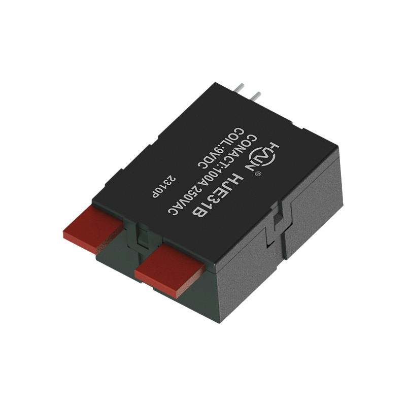
Product Definition: The HJE31B-100A is a split-type 7P DIN rail relay designed specifically for three-phase power systems. It features current monitoring, relay protection, and energy metering functio...
See Details
The Powerful Core of the PDU! The HJE12A-120A is a PCB-based through-hole high-power relay designed specifically for rack-mount power distribution units (PDUs), aiming to achieve PDU miniaturization, ...
See Details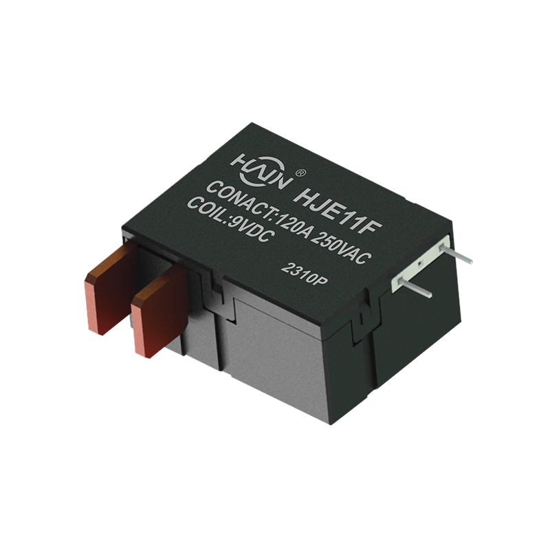
Product Definition: The HJE11F-120A-250VAC is a high-performance magnetic latching relay designed specifically for undervoltage protection systems. It supports a maximum current of 120A and is suitabl...
See Details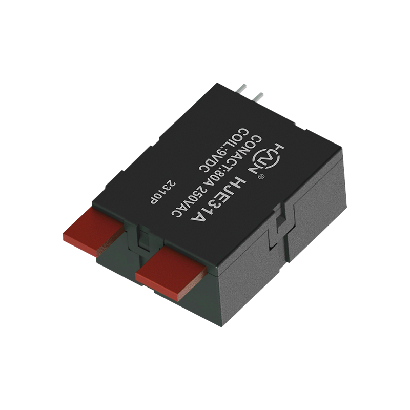
Product Definition: A bottom-in, bottom-out relay specifically designed for 2P DIN rail meters, aiming to improve installation efficiency and system reliability through optimized wiring structure.
See Details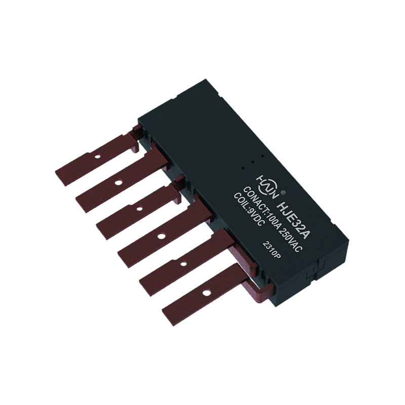
Product Definition: The HJE32A-100A is an innovative integrated three-phase relay designed specifically for 7P DIN rail meters. It aims to perfectly integrate three-phase metering and control, signifi...
See Details
 Add.
Add.
|
No. 707, Yanyu Road, Yucheng Town, Haiyan County, Jiaxing City, Zhejiang Province, China
|
 Phone
Phone
|
+86-188-5739-7300
|
 Email.
|
alio@hj-relay.com
|
Copyright @ Huajin Technology Jiaxing Co., Ltd. All rights reserved.
